
Parts 1 and 2 of this article can be found in the December 2015 and January 2016 issues of STRUCTURE magazine.
The newly accepted design of the Quebec Bridge maintained the 1,800-foot main span with straight upper and lower chords on the anchor and cantilever spans. All of the parts, especially the lower compression chords, were much larger than the Phoenix Bridge/Cooper design.
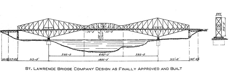
Final plan of trusses.
Instead of building the suspended span out from the ends of the two cantilever arms, they decided to build it off site and lift it into place. The suspended span was built starting in May 1916 at Victoria Cove, approximately three miles below the bridge, and was finished in July. The plan was to float it under the bridge and lift it into place, hanging it from suspenders attached to the ends of the cantilever arms. The span, with its length of 650 feet and weight over 5,000 tons, was floated into place on September 11 and connected to the lifting jacks. What happened next, if it hadn’t happened would not be believed, but the Quebec curse reappeared. The official report of the Board of Engineers, which now had H. P. Borden as a member, described the series of events on that fateful day.
“Preparations for floating were completed about September 1, 1916, but the range of tides, at this date, were not suitable. It was felt by the contractor, however, that several days could be spent to advantage in drilling their engineers and men in the various operations and in making a final inspection of the equipment and appliances. The next series of high tides occurred on September 11, and, weather conditions being favourable, the span was floated at 3:40 a.m. and by 4:40 a.m. it was being towed out into the river. Four small tugs and one large tug were attached to the downstream side, with two small tugs upstream. As the tide was running strong, the tugs had little to do but guide the span on its trip up the river. At 6:35 a.m. the span reached the bridge site and at 7:40 a.m. the lifting hangers at all four corners had been connected. At 8:50 a.m. the jacks began lifting, and during the third lift of two feet the scows floated clear, leaving the span suspended about 20 feet above the water. After another lift of two feet, work was stopped to allow the men a period of rest and breakfast.
Up to this point the entire operation of floating the span and connecting it to the lifting hangers had worked exactly according to schedule. Nothing occurred that had not been foreseen and provided for. There was no wind, and every condition was favourable. As the work remaining to be done was simply a repetition of mechanical operations which had already been successfully performed, it was felt that most difficult part of the work had been satisfactorily accomplished.
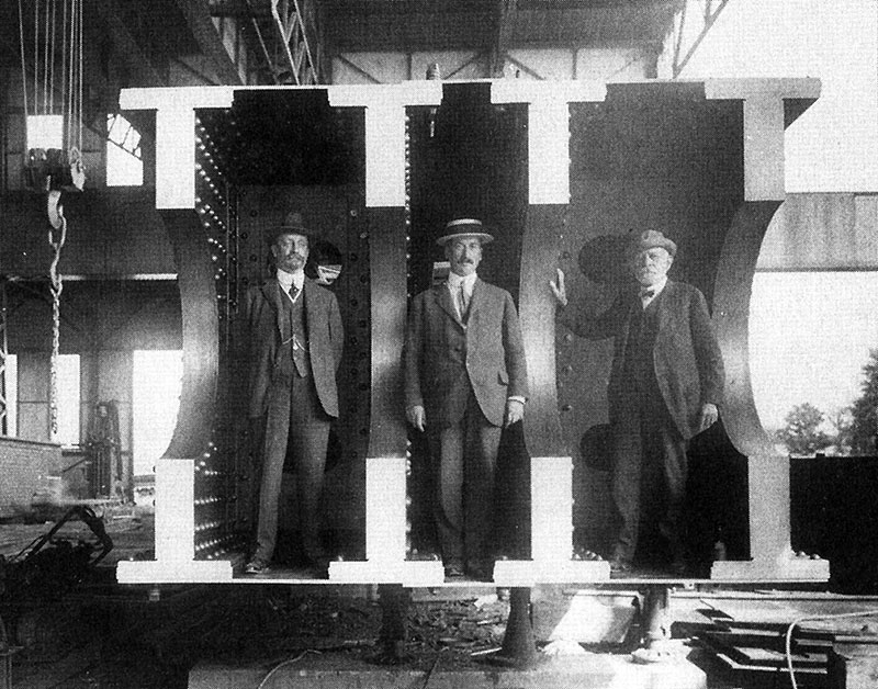
New lower chord at pier, Modjeski, Monsarrat, Schnieder (l to r).
At 10:30 a.m. jacking operations were resumed and one more lift made. The pins had been inserted connecting the lifting links to the fixed jacking girders, thus transferring the load directly to the cantilever trusses. The load on the jacks had been released and they were being lowered for another lift when, at 10:50 a.m., a sharp report was heard and the span was seen to slide off its end supports into the river.”
Unlike the first failure where there were few eyewitnesses to the collapse, this time the press, photographers and officials of the government and the Board were on hand to witness the failure. Engineering News reported “many prominent engineers from the United States and Canada were on the suspended span when the lifting operations began. At the intermission in the jacking operations, they came ashore. That saved their lives…” They also reported that “both cantilever arms of the structure were thronged with many prominent engineers who had come to see the crowning achievement of the Quebec Bridge’s history.” The first reports of the failure came to Engineering News just before they went to press for their September 14 issue. Based upon limited information, they wrote: “The engineering world was amazed when the south cantilever of this great bridge fell nine years ago; but words are inadequate to express its sensations at the news that again this great bridge enterprise has suffered an unprecedented disaster.”
Thirteen men were killed this time, with fourteen injured. Once again an intensive investigation into the cause of the accident was launched. It was clear to all that the truss had fallen off of the southwest supporting girder. The designers had used cruciform steel castings at each corner to provide for movements about two perpendicular axes.
The investigating team was confident that this was the sole cause of the failure; but, to leave no stone unturned, they investigated three other possible failure mechanisms. The most significant was that of a “failure of the suspended span through some error of design.” Their conclusion was that the failure was indeed due solely to a failure of the casting. The ends of the cantilever spans had deflected seven and one half inches when they were subjected to the load of the suspended span. When the span dropped, the arms were seen “to spring violently upward, setting up severe vibrations and oscillations.” A thorough examination of the structure showed “no evidence of injury or distortion of any kind.” The engineering journals of the world wondered if it would be possible to “raise this span from the bottom of the river, in water about 200 feet deep?” No one had any thought that the span could be reused, but they were discussing reclaiming the truss for its scrap value. The Engineer, London wrote “the span has in all probability fallen more or less in position; and if it is found on inspection to be indeed worth saving, it is not impossible that the arms of the cantilevers may serve as cranes to raise it from the bottom.” This suggestion was not followed, and the span still rests at the bottom of the river.
On September 13, 1916, the St. Lawrence Bridge Company accepted full responsibility for the failure and took “immediate steps to replace the span.” The bridge company was in the process of tooling up to make shells for the war effort, but still had enough of the original equipment available to fabricate a new truss which followed the same lines as the previous span with the exception that more nickel steel was included in the upper lateral bracing system. Carnegie Steel was able to fit in the rolling of the new steel for the span even though it to was actively involved in the war effort. The Board and the Bridge Company decided that the entire lifting apparatus would have to be rebuilt due to excessive deformations of the lifting links occasioned by the fall.
Work on the new suspended span got under way at Sillery on June 4, 1917, with the span being completed on August 27. It was floated into place on September 17 or just over one year after the failure. This time, however, the erectors were even more careful than they were previously and had modified the end supports for the truss. The new device did away with the necessity for the second pin, which was responsible for the cruciform type of bearing originally used. The span was jacked and lifted into place over the next three days, with the final pins connecting the permanent suspension bars to the centre span being driven at 4 p.m., Thursday, Sept. 20, 1917. The Engineering News-Record which had just been formed by the merging of Engineering News and Engineering Record reported the moment as follows:
“The seventy-fifth lift followed immediately, and locomotive cranes were run out to all four corners with pin-driving cages and pins. At the end of the stroke, at 3:25, the first of eight pins was driven. The clearances were perfect, and each long pin slipped through its eye bars with a few taps from a short rail swung by about ten men. Every ringing blow of the rails stirred the onlookers. And when at 4 o’clock the last foreman shouted, “Right, here!” all restraint among workers and watchers was lost. The crane whistles on the bridge picked up the men’s cheers and the river boats passed the signal down to the City of Quebec, where (by the Mayor’s proclamation) every whistle and bell and automobile horn was turned loose, and flags and buntings were thrown to the breeze everywhere, for Quebec realized that its dream of thirty years had come true.”
The Engineer, London wrote “one of the greatest, if not the greatest, feat of bridge engineering the world has ever seen was brought to a successful conclusion, on Thursday, September 20, 1917 at 4:01 p.m., when the 10-inch pin connecting the two sections of the Quebec Bridge to the ends of the cantilever arms were driven.” The Canadian Engineer proclaimed “Canadian Engineering Has Triumphed at Quebec.”
The dedication of the bridge by the Prince of Wales was similar to that of the Firth of Forth Bridge 29 years earlier. This time, however, no one was knighted, as the project had been from its new start in 1908 a team effort. The main players were Ralph Modjeski who had been a member of the Board from the beginning, C. C. Schneider who had a connection with the bridge from 1907 when he was a consultant to the Royal Commission to his death in early 1916, and C. N. Monsarrat who was chief engineer for over eight years. The engineers, fabricators, and erectors of the St. Lawrence Bridge Company under the leadership of Phelps Johnson had built a bridge with a quality of workmanship unmatched in its day.
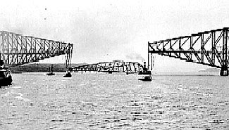
Suspended span collapsing into the St. Lawrence River.
The bridge was the product of American and Canadian engineering and bridge fabrication. It still carries railroad and highway traffic across the river. The lessons learned were hard ones, but never again would all the responsibility of a major project be placed on the shoulders of one, or even two men, but would be team projects with all members of the team working towards a successful completion. Checking at all stages of construction is now standard practice. Having men on the site during construction, with the authority to act, sadly lacking at Quebec, is also now standard practice. While it is still not possible to test full size compression members such as were designed at Quebec, we are able to test large members and through experience have designed many large compression members for bridges and buildings. As the result of the failure, the United States Congress authorized the construction of a $1,750,000 testing machine designed by A. H. Emery for the United States Bureau of Standards and installed it at the Watertown Arsenal.
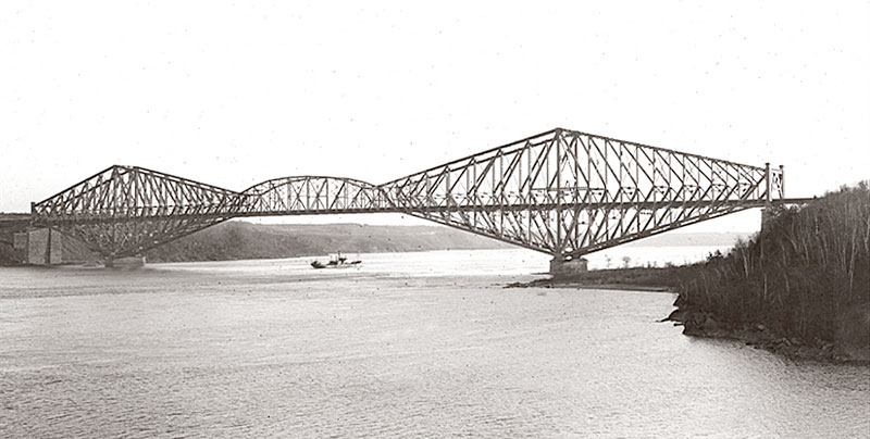
Quebec Bridge 2008.
The bridge, with its 1,800-foot main span, was the longest span bridge in the world for many years and still is the longest span cantilever bridge in the world. In 1987, it was designated an International Historic Civil Engineering Landmark by the American and Canadian Societies of Civil Engineering.▪