
This article summarizes the author’s experience in developing a structural model to analyze and design a structure for the Victor Valley (California) Wastewater Reclamation Authority that is approximately 50 feet wide by 300 feet long. Because the structure has significant horizontal and vertical irregularities, and is in a high seismic area of southern California, design codes specified three methods of analysis: (A) Modal Response Spectrum Analysis (MRSA) for structures with horizontal irregularities; (B) Tank Hydrodynamics for water basins; and (C) Equivalent Lateral Force (ELF) for regular structures. The three process-integrated areas are separated from each other by expansion joints and are shown in Figure 1, in which some roof and wall segments are removed to display internal components. Overall design of the facility was completed by the office of Carollo Engineers, Inc. in Phoenix, Arizona.
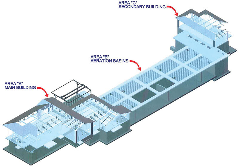
Figure 1: Water treatment complex – overall view.
Area A – Main Building
The main floor of the building is at grade, but the roof is divided into three different levels in order to lower each level as much as possible and minimize the visual impact of the complex on the surrounding residential neighborhood. One roof is approximately 20 feet above grade, a second is 18 feet-8 inches above, and the third is approximately 16 feet high. On each roof is an elevated tile mansard that surrounds several units of HVAC equipment. The tile is supported by metal deck over small steel trusses that are bolted to the concrete topping of a 5½-inch deep composite steel deck, which forms the main roof diaphragm. Bearing walls are 12-inch masonry units that are integrally colored and partially treated with a stucco finish. For details of the author’s method of modeling composite diaphragms, foundation soil springs, and ‘cracked’ masonry, as well as the ELF method of analysis, refer to Modeling and Analysis of a Masonry Building on Piling (March 2013, STRUCTURE magazine).
The first step was to create a computer model and use it to determine the seismic base shear of the structure in accordance with the ELF of ASCE 7 paragraph 12.8, with a response modification factor R=5.0, importance factor I=1.25, and Site Class D. The resulting value was 245 kips.
In accordance with ASCE 7 table 12.6-1 for Seismic Design Category D with horizontal irregularities and paragraph 12.7.3, the next step required performing MRSA in the north-south and east-west directions. Eighty modes produced more than 90% mass participation in each of the principal directions. The redundancy factor was 1.0 to check drift and torsional irregularities. Dividing modal response parameters by R/I (i.e., 4.0), multiplying calculated displacements by Cd/I (i.e., 2.8), and combining the various modes using the Complete Quadratic Combination (CQC) method resulted in base shears of 124 kips in the north-south direction and 156 kips in the east-west direction.
The next MRSA included application of a load factor to scale the design base shear up to 100% of the ELF base shear. Since California Building Code Section 1615A.1.8 only applies to schools and hospitals, the final design was based on 85% of the calculated stresses. Displacing certain concentrated load masses associated with equipment in a direction orthogonal to that of the earthquake satisfied the code requirement for accidental torsion. Although not required by ASCE 7 paragraph 12.9.5, the accidental torsion was amplified in both directions. This conservative addition is intended to help preserve the integrity of the architectural wall finishes and stucco, which also includes fiber reinforcement.
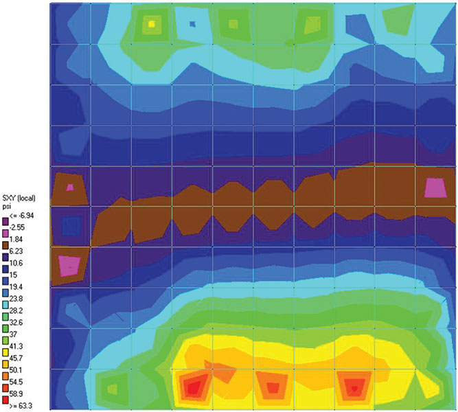
Figure 2: Roof diaphragm in-plane shear stress.
Combining the results of north-south (Z-direction) and east-west (X-direction) modeling using the relationship of 1.0X and 0.30Z (and vice versa) produced the critical design wall and diaphragm forces. The redundancy factor in the second MRSA was 1.3, based on ASCE 7 paragraph 12.3.4.2 and the configuration of the masonry shear walls. Design of collectors, such as the beams and columns under discontinuous shear walls at the ground floor, included an overstrength factor of 2.5. Figure 2 represents the area A high roof diaphragm shear stress, which the model shows concentrated at the center of elements, for the roof on the right side of area A. However, some modeling references (e.g., NEHRP Seismic Design Tech Brief #5) recommend distributing the concentration over a larger deck cross-section based on the ductility of the steel deck with reinforced concrete topping. Modeling with smaller finite elements is another alternative to produce a finer distribution of visible stresses. Figure 3 represents the shear stresses in the wall supporting two roofs that are at moderately different levels.
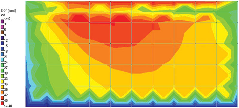
Figure 3: Wall in-plane shear stress at roofs separated 32-inch vertically.
Area B – Aeration Basins
The basins are approximately 20 feet deep and the concrete walkways are a few feet above surrounding grade. Fiberglass deck panels span the basins between the walkways. Interior baffle walls are without walkways and serve as process weirs. For a partial rendering of the basins, see Figure 4.
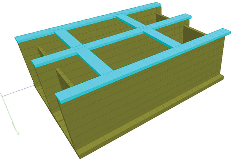
Figure 4: Partial view of area B baffle walls and walkways.
An initial analysis using proprietary software summarized the trapezoidal static, hydrostatic, and hydrodynamic pressures of the soil and liquid on the basin walls, in accordance with the linear distribution methodology of ASCE 7-05. The estimated wave sloshing height in the north-south direction due to seismic hydrodynamic loading is 1 foot, and freeboard is approximately 3 feet. In the east-west direction, sloshing height is 4 feet and an uplift resistance of 60 psf has been specified on the covers. The consequences of the impulsive and sloshing effects of the liquid, the impulsive effect of the walls, and the static and dynamic effects of the soil generated pressures for four load cases that were incorporated into the model: (1) backfilling operations during construction with equipment surcharge; (2) unbackfilled during construction and filled for the leak test; (3) backfilled and empty during a seismic event; and (4) unbackfilled and full during a seismic event.
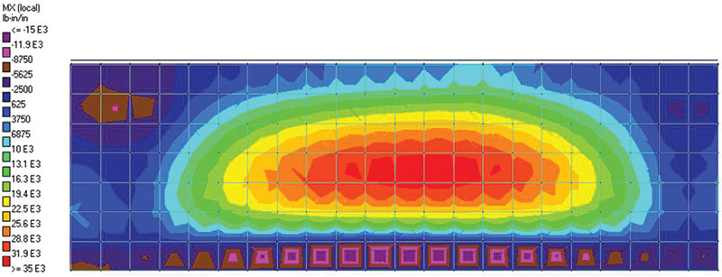
Figure 5: Vertical bending on exterior basin wall in Figure 4 (walkway at top).
Figures 4, 5 and 6 suggests the benefits of the model for accurately determining the effects of walkways and interior baffle walls on the overall design. The analysis model included the basin mat, walls, and walkways under the pre-determined pressures for the four load cases. Figure 5 represents the vertical bending in the wall for Load Case 2, confirming the influence of the walkways in developing a large positive moment near the center of the wall and reducing the negative moment at the base (note sore spot at upper left due to interior wall). Figure 6 represents the horizontal bending in the walkways for the same load case, and suggests the influence of the (hidden) interior baffle walls.
Figure 6: Horizontal bending on walkways.
Area C – Secondary Building
The main floor of the secondary building is at grade, and its main roof is approximately 14 feet above grade. The basement houses a series of process pumps, while the ground floor supports an electrical equipment room. The main roof supports HVAC equipment surrounded by a mansard. The analysis model included the foundation mat, bearing walls, and composite steel deck diaphragm using the same methodology as previously stated. The ELF method for a regular structure produced the base shear and seismic stresses.
Conclusion
The author is interested in learning how other structural engineers are modeling earthquake loads and stresses, and meeting the ever-growing complexity of seismic code requirements. Readers are encouraged to contact the author to share alternate methods. The author also wishes to thank the Orange County, California, office of Carollo Engineers for its thorough review of the seismic design of this project, which resulted in numerous improvements. One important example was the design of the ‘knee brace’ that interconnects each beam purlin (collector) at the vertical irregularity between two adjacent roofs, thereby significantly reducing ‘out-of-plane’ stresses in the top wall panel between those two roof levels.▪