
Nondestructive and Minimally Invasive Techniques
In a STRUCTURE® article published earlier this year, the author discussed some of the components of a nondestructive evaluation (NDE) program for existing masonry structures, and what types of information could be obtained through such methods. This article aims to elaborate on the procedures and techniques used to investigate existing masonry structures and diagnose potential issues.
Flatjack Tests
From a structural design standpoint, some of the most important properties of existing masonry include strength, stiffness, and in situ stress. Flatjack testing methods are some of the most valuable tools available for measuring masonry resistance to loads as well as the existing stress that the masonry is currently experiencing. First, it’s important to distinguish the type of test to be specified, as the information provided by each test method is different.
ASTM C1196, Standard Test Method for In Situ Compressive Stress Within Solid Unit Masonry Estimated Using Flatjack Measurements, provides a procedure for measuring the existing state of vertical compressive stress within an unreinforced solid masonry wall. This information is of particular use when supplemental supports are designed for areas where plans call for portions of existing masonry walls to be removed. The results of this method have also been used to verify analytical models, complicated load paths, and flexural bending moments across a wall section. In this test, a single stress-relieving horizontal slot is cut in a masonry bed joint in the area the information is desired. A series of gauge points placed above and below the slot help to precisely measure the vertical distance that the masonry drops after cutting. A single Flatjack is inserted into the slot and pressurized at increasing increments while the distance between gauge points is measured, until the original distance between gage points is restored (Figure 1). The Flatjack pressure required to restore the original masonry position generally corresponds to the in situ stress, after the necessary calibration and area factors are applied.

Figure 1: Single flatjack test used to determine masonry in situ stress.
ASTM C1197, Standard Test Method for In Situ Measurement of Masonry Deformability Properties Using the Flatjack Method, provides a means for measuring masonry stiffness and estimating masonry compressive strength, which are often the most important masonry properties in design and retrofit. In this test, two horizontal slots are cut with five courses of masonry between them. Both Flatjacks are pressurized together while monitoring the surface strain of the masonry between them (Figure 2); the result is a compressive strength test within the wall that produces a stress-strain curve (Figure 3). In order for the test to be effective, the Flatjacks must react against masonry which is rigid enough that only the masonry between the Flatjacks deforms during the test. Generally, this is not a problem below the test location as long as the test is not performed directly above an opening, since most walls are supported by foundations that won’t deflect during the test. Ensuring that enough dead load is present on the masonry above the test location can be more difficult, especially for single story buildings or test locations near the roof. Without enough overburden pressure, the upper Flatjack can actually lift the portion of the wall above it, limiting the maximum applied pressure to the test area.
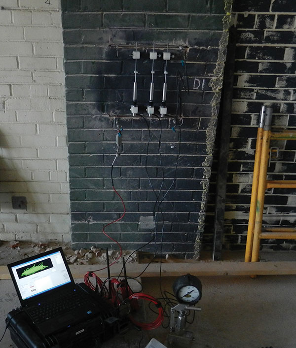
Figure 2: Flatjack deformability testing to measure masonry elastic modulus and estimate compressive strength.
Figure 3: Masonry stress-strain curve generated by flatjack deformability testing.
Masonry shear strength is measured by ASTM C1531, Standard Test Methods for In Situ Measurement of Masonry Mortar Joint Shear Strength Index. In this test, mortar is cleared from both head joints of a single unit. A single Flatjack, specially sized to match the brick end, is then inserted into one of the empty head joints, while instrumentation such as a dial gauge is used to measure displacement across the other. The Flatjack pressure is slowly increased until it causes the masonry unit to move toward the empty head joint (Figure 4). The pressure required to induce movement is recorded and used to calculate the mortar joint shear strength index. Unlike the Flatjack deformability test, having a minimal amount of dead load above the shear test is advantageous. Because normal stress contributes to the bed joint shear resistance, this normal stress must be estimated and then subtracted from the measured joint shear strength using the procedure described in the International Existing Building Code. One way to reduce the effect of normal stress on the shear test is to perform the test below an opening or near the top of the wall.
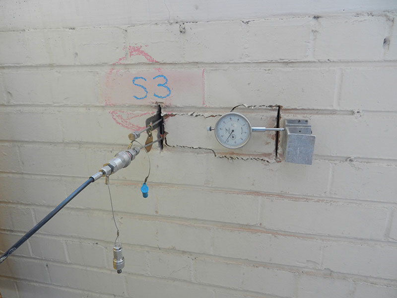
Figure 4: Masonry shear strength testing using a specially-sized flatjack.
Surface Penetrating Radar
The use of Surface Penetrating Radar (SPR) for masonry investigation does not follow a standardized procedure, but rather depends on the interpretation and experience of the user. In the right hands, SPR can be most useful in locating embedded objects such as metal reinforcing or conduit, locating bond courses, and assessing the extent of anomalies, voids, or ungrouted cells. The equipment often consists of a handheld or wheeled antenna, processor, and output screen. The antenna transmits microwave energy and then collects the reflected signal as it bounces back. What the user sees on the screen is the result of this energy being reflected back at various times, which relate to depths of different materials. Metals, for example, are highly reflective to radar energy and thus SPR is very effective at locating reinforcing bars and other metal objects within masonry walls (Figure 5). Air, on the other hand, is not particularly reflective to radar energy. Since almost none of the transmitted energy is reflected back by these empty spaces, an experienced user will be able to differentiate between air and solid material. Therefore SPR can be used to locate cracks, voided areas, or hollow masonry cells.
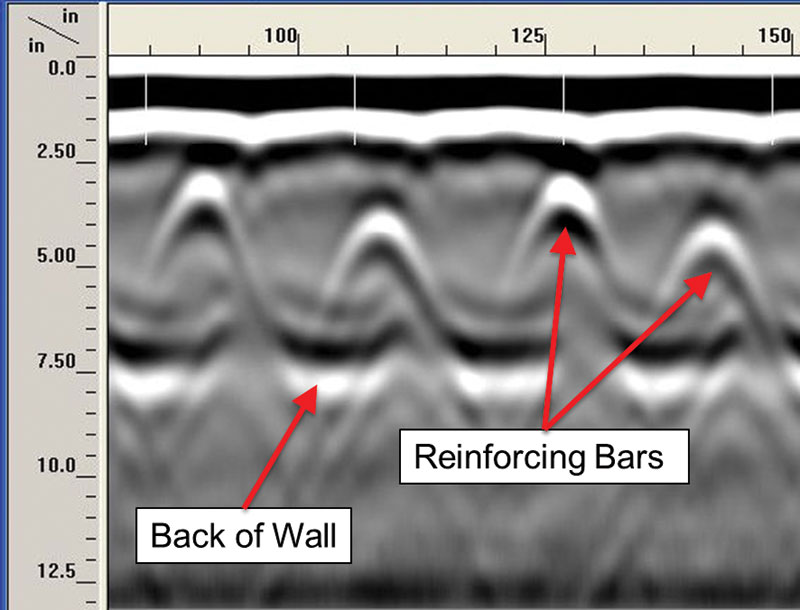
Figure 5: Surface Penetrating Radar output image showing masonry wall thickness and reinforcing bars.
SPR is most effective on walls that are dry because wet areas are highly attenuative to microwave energy, thus reducing its effective penetration depth and limiting the information available to the user. Since the exterior face of a masonry wall tends to dry out before the internal portion does, significant moisture can still be present inside the wall even if the outer surface appears dry. It may be necessary to wait for an extended amount of time for masonry walls to dry after a severe weather event before performing SPR observations, depending on local climates. A moisture meter should always be used to confirm conditions if moisture is suspected.
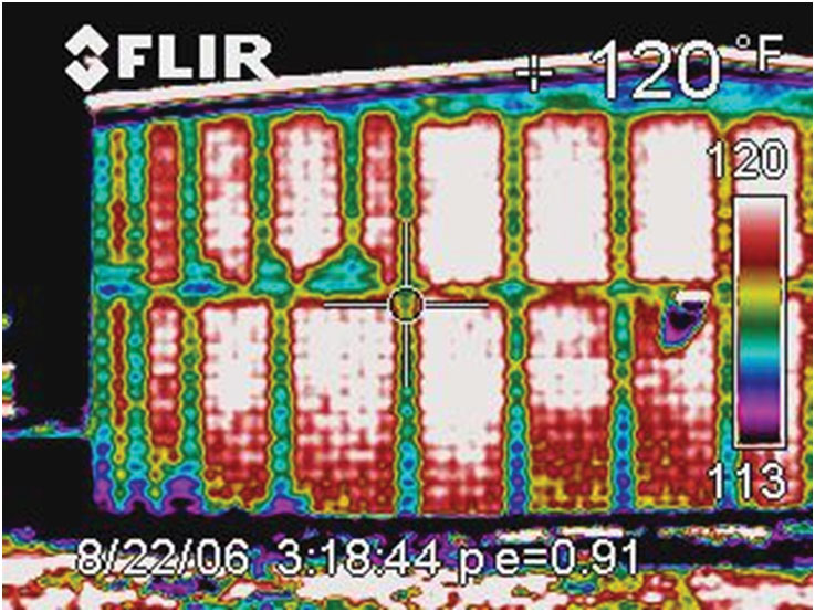
Figure 6: Infrared Thermography image used to quickly distinguish between grouted and hollow cells in concrete masonry construction.
Infrared Thermography
Masonry’s thermal mass and thermal transfer properties make infrared thermography (IRT) an ideal method for investigating potential anomalies. The cost of infrared equipment has decreased in recent years, while quality has continued to improve. As it relates to masonry investigation, IRT is most useful in locating temperature differences at specific areas, which can indicate the possibility of internal anomalies. One such anomaly is the potential for excess moisture and leaks. The temperature difference between wet masonry and dry masonry, due to evaporative and other effects, will produce distinctive appearances between the two when viewed using infrared equipment. Larger air voids, such as those left by unfilled cells, can also be detected using IRT (Figure 6). For IRT to work effectively on masonry structures, however, there needs to be a large enough temperature difference between the building and the surrounding air. This is usually best achieved in early morning or late evening, when the air temperature is changing. In the morning, the sun begins to warm the masonry while the grouted cells stay cool. In the evening, the opposite occurs; empty cells, voids, and wet areas become cool while the stored heat from the day remains in the wall. IRT also works well when there is at least a 30° temperature difference between interior and exterior wall surfaces.

Figure 7: Borescope view of a masonry wall cavity and veneer anchors.
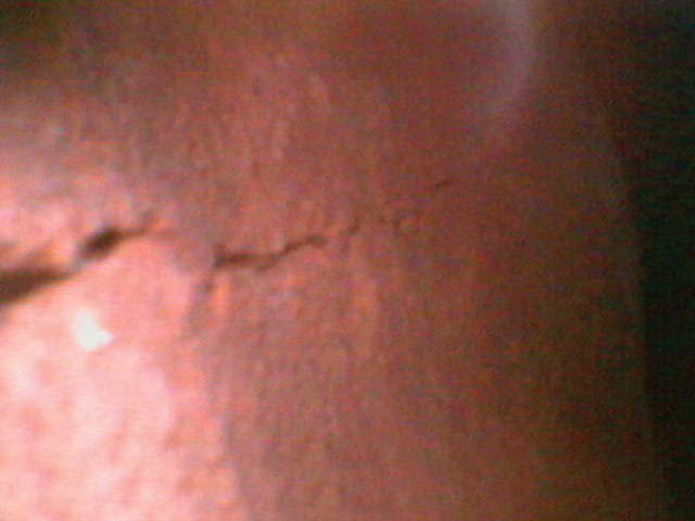
Figure 8: Borescope image of a crack forming on the back face of a veneer panel.
Borescope
Images observed via fiber optic borescope are a useful way to view concealed conditions without removing or damaging large portions of the wall. A small borehole, usually less than the thickness of a mortar joint, is the only opening needed to insert the probe. A borescope can be used to view the condition of connectors (Figure 7), cracks or deterioration on the back faces of units (Figure 8), and excess mortar within wall cavities.
Pulse Velocity
Pulse velocity testing following ASTM C597, Standard Test Method for Pulse Velocity Through Concrete, has been successfully used to evaluate masonry structures for cracks, deterioration, and construction quality. The equipment operates by sending a pulse of mechanical energy through the face of the masonry, and measures the length of time to receive the signal on the opposite face or on the other side of a suspected discontinuity such as a crack. Differences in velocity between known intact areas and possible deterioration can confirm these suspicions, and a decrease in velocity at the same location over time could indicate worsening conditions. Evaluation of energy loss (attenuation) and frequency characteristics provides additional information on the internal quality of the masonry.
Water Penetration
Identifying moisture paths and water penetration through masonry walls, or evaluating water repellent surface treatments, are accomplished through the use of a spray chamber as described by ASTM C1601, Field Determination of Water Penetration of Masonry Wall Surfaces. The test method is performed using a 12-square-foot chamber attached to the wall, which allows the user to apply a prescribed water flow and pressure to the wall surface. The chamber has to be sealed to the wall surface so that no leakage occurs from the chamber during the test. Typical conditions of this test include a water flow of 3.4 gallons per square foot per hour at 10 pounds per square foot (psf) air pressure, but these may be adjusted based on local weather data. Water loss into the wall surface is recorded for a minimum of 4 hours, and any observed water penetration to the opposite wall face is reported.
Spray tests can also be performed to gain understanding of wall leakage potential, especially around windows, following AAMA 501.2, Quality Assurance and Diagnostic Water Leakage Field Check of Installed Storefronts, Curtain Walls, and Sloped Glazing Systems. This test uses a specially sized nozzle and a prescribed pressure of 30-35 pounds per square inch (psi). If leaks are discovered during the test, specific components are then sealed off to determine the moisture entry paths.
A direct evaluation of wall drainage and water collection systems may be performed using ASTM C 1715, Standard Test Method for Evaluation of Water Leakage Performance of Masonry Wall Drainage Systems. In this test, a series of tubes deliver water directly to the drainage cavity and the ability of the system to collect and redirect water to the exterior is observed.
Pachometer
Location of metal objects such as veneer ties and joint reinforcing within masonry walls may also be facilitated through the use of an eddy current pachometer. If reinforcement size is known, the pachometer is also useful for estimating the depth of masonry cover. The pachometer is especially useful for locating smaller metal objects such as anchors and veneer ties, which are difficult to locate using SPR due to their smaller reflection surface.
Corrosion Potentials
Metal reinforcement corrosion potentials, also referred to as half-cell potentials, are evaluated using ASTM C876, Standard Test Method for Corrosion Potentials of Uncoated Reinforcing Steel in Concrete. A direct electrical connection first needs to be made with the reinforcing steel, which is often accomplished by drilling or chipping the masonry to expose a small portion of the bar and attaching a clamp. This also requires that the reinforcing be located prior to performing the corrosion potential measurements. The electrical potential of the reinforcing metal is measured against a copper-copper sulfate reference electrode with a voltmeter. Measurements are made along the reinforcing by placing the electrode on the pre-wetted masonry surface and recording the potential difference displayed by the voltmeter at regular intervals. Corrosion potentials more negative than -0.35 V indicate a high probability of active corrosion at that location. Measurements can only be made at reinforcing with an electrical connection to the location that is clamped to the voltmeter; so, in masonry, this usually means along a bond beam or a vertically reinforced cell.
Conclusion
The proper selection and use of NDE methods are a valuable, and in some cases necessary, approach to determine properties required for design or use of existing masonry structures. In historic construction, destructive probes may not be allowed or must be kept to a minimum. In new construction, NDE has been used as a form of quality control to verify project requirements are met, especially for placement of grout, reinforcing bars, and veneer anchors.
The nondestructive and minimally invasive diagnostic techniques described here allow effective evaluation of existing masonry structures without excessive damage and expensive sample removal. Finally, NDE methods provide the design engineer with confidence that material properties and conditions are known, and confident engineers provide the most cost-effective solutions for repairs or retrofit.▪