
A Composition of Dramatic Concrete and Steel Structures
When the newly built San Diego Central Library opens its doors in autumn 2013, it will be a landmark project for both the City of San Diego and the project’s design and construction teams alike. The project presents multiple unique challenges in its many unique structural frame components, most of which are architecturally expressed with minimal treatment. Prevalent among the structural design elements are the cast-in-place architectural concrete frame beams and columns, exposed concrete waffle slabs, and the iconic steel and aluminum dome structure that provides shade and acclimatizes the eighth floor main reading room.
The project encloses 504,000 square feet on its nine above-ground floors and includes reader seating for 1,200 persons, 407 computer stations, 22 wifi-enabled study rooms, meeting rooms and gallery/exhibition spaces. The site is also home to a new 350-seat community auditorium building. Two subterranean levels provide parking for 250 autos. The project targets a LEED Silver certification. Figure 1.
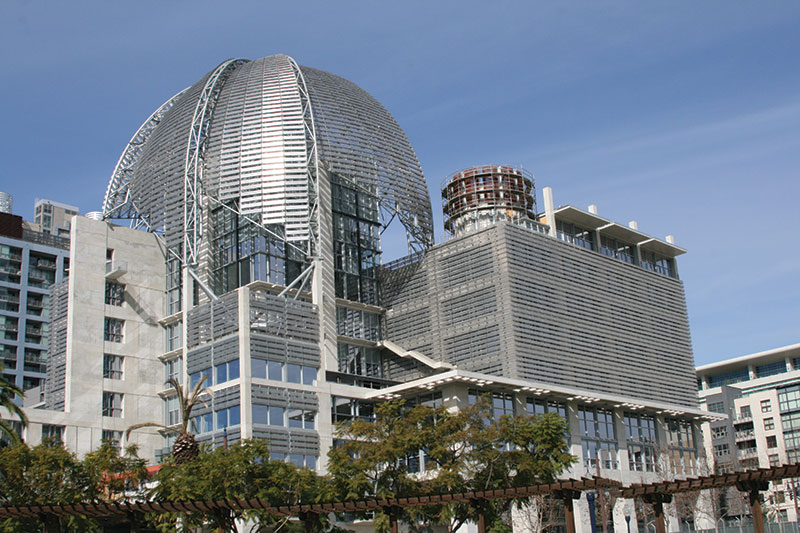
Figure 1: The San Diego Central Library in March 2013.
Special Moment Resisting Frame
Selection of vertical and lateral load-resisting systems for the library is dictated in good part by the building’s use. Programmatic requirements for an open and versatile floor plan with natural daylighting, heavy live loads, and the necessity for perimeter retaining walls below grade lend to employment of a reinforced concrete special moment-resisting frame (SMRF) above grade and reinforced concrete shear walls below grade. Sizing and shapes of SMRF columns are dependent on their location in the structure and on architectural considerations. Moment frame columns occur at the perimeter of the ninth floor, trace down through the structure, and continue below grade to retain ductile detailing to the foundation level. Frame columns and frame beams are also introduced along different lines as the footprint of the floors increases top-down. SMRF columns prevail at 75 inches (1.9 meters) square, but grow to as large as 72 x 92 inches (1.8 x 2.3 meters) in the reading room and east colonnade. Typical moment frame beams are upturned 5 feet (1.5 meters) deep by 27 inches (0.7 meters) wide. Locating the SMRF columns and beams along the perimeters of the floor plates allows the interior of the floors to be supported by smaller gravity columns, which supports the design intent of an open floor plan. Gravity columns are minimized to 34 inches (0.9 meters) square below grade and 30 inches (0.8 meters) square above grade. Figure 2.
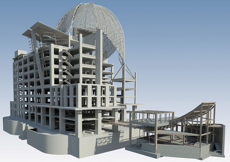
Figure 2: All structural and architectural components were modeled, coordinated, and 4-D scheduled thru Revit, Vico, and Synchro. Courtesy of Turner Construction.
Waffle Slabs
The building is designed for a minimum live load of 150 pounds per square foot (psf) at and above the ground level, with limited areas to receive compact shelving designed for 300 psf. The nearly 350,000 square feet of typical floors employ a 23-inch (0.6 meter) thick waffle slab with waffle voids spaced four feet (1.2 meters) on center. The decision for waffle slabs also accommodates the 32-foot (10-meter) wide column bays. The aesthetic of the waffles as viewed from below, as an exposed ceiling, is architecturally appealing and also possesses sound-attenuating properties. Strategic use of in-slab beams, combined with upturned frame beams at the floor plates’ edges, allows maximum daylighting of the interiors via clerestory glazing set between the upturned beams and waffle ceiling soffits. Typical floor to floor heights are 15 feet (4.6 meters).
Heat of Hydration Issues
Heat of hydration was a very real concern, since many concrete frame elements are in excess of six feet square and the concrete gravity arch reaches dimensions of thirteen feet radially by six feet wide. Initial mock-ups using the specified cement resulted in internal curing temperatures exceeding 250 degrees F in the first 24 hours. This exceeded the maximum allowable internal curing temperature of 180 degrees – the upper threshold established for control of thermal cracking and ensuring the long-term durability of the concrete. Additional trial batches were ordered to test heat characteristics and compressive strengths of mixes utilizing alternate architectural grade cements. While the alternate trial batches continued, nine mockups were performed to test non-technical heat mitigation strategies. Non-technical controls included placing mass concrete elements as early as possible in the morning to take advantage of low ambient temperatures, batching concrete with chilled water or ice depending on the season, and limiting concrete deliveries to five cubic yards per truck for the largest components. The non-technical strategies were found to effectively maintain concrete consistency between lifts without the need to introduce water at the jobsite – critical to achieving uniformity of color in the finish product. A single mix design of 6,000 psi concrete using locally available Colton, California Type-I cement and a set-retarding admixture was selected, and is employed for all architectural concrete applications within the building.
Architectural Concrete Aesthetic
The program calls for all above-grade concrete to be architectural as-cast and fair-faced, utilizing a high albedo architectural grade cement and incorporating an ACI Class A finish. Chief among the preferences for the concrete aesthetic are a light colored matte finish, minimal appearance of forming hardware, and a custom pattern that calls for plywood to be cut to random sizes and oriented to create an organic “quilted” effect. Slight imperfections and offsets are desirable to create an aged appearance. The combined application of mass concreting issues and architectural concrete program requirements resulted in a series of fifteen mock-ups and other research and development efforts to test cement options, concrete mix designs, plywood types, tie design strategies, form releases, and rustication strips.
Structural concrete and non-structural concrete components employ different treatments as a visual telling of their role in the building. Ties are located in structural elements at wide spacings on a static series of datums: 5-foot on center (o.c.) vertically and 4-foot o.c. horizontally. A tighter tie spacing ranging from 2-foot o.c. to 4-foot o.c. is applied to non-structural concrete depending on the application. To achieve the vision of a quilted aesthetic, hundreds of concrete shop drawings were translated from the BIM model (Figure 2) to account for every plywood seam and tie-hole in all exposed columns, beams, edges of slabs, and walls as well as in custom structures such as the concrete gravity arch. Due to the complexity and non-repeating nature of the plywood patterns, an unusual step was needed: the creation of formwork fabrication and placing drawings. These drawings were provided to field crews to assist with prefabrication and production in placing formwork. For example, each column form incorporated the deliberately located random patterns into the fascia sheeting, each with wholly unique seam layouts, such that no two were alike. Since forms had to be reused throughout the structure, placing drawings included production notes to assist field crews with a pre-planned strategy to “mix-up” the stock of forms, or rotate column forms from their prior axial orientation, from one pour to the next to further give the allusion of random, non-repeating patterns in the concrete. The regular pattern of the ties, juxtaposed with the scattered seams of plywood sheeting, creates a unique craftsmen quality in the finish product.
Energy Efficiency
As-cast architectural concrete contributes to energy efficiency by minimizing capital costs compared to other building finish systems since surface treatments involve only minor touch-up. The reduced expense for finish systems also translates to reduced maintenance and life cycle costs for the Owner. End-user energy demand is reduced significantly by way of the structure’s concrete envelope and its inherent thermal mass, which reduces day-time cooling needs and evening warming of the interior spaces. Aluminum sunshades on south and east facing clerestory windows further mitigate daytime heat gain.
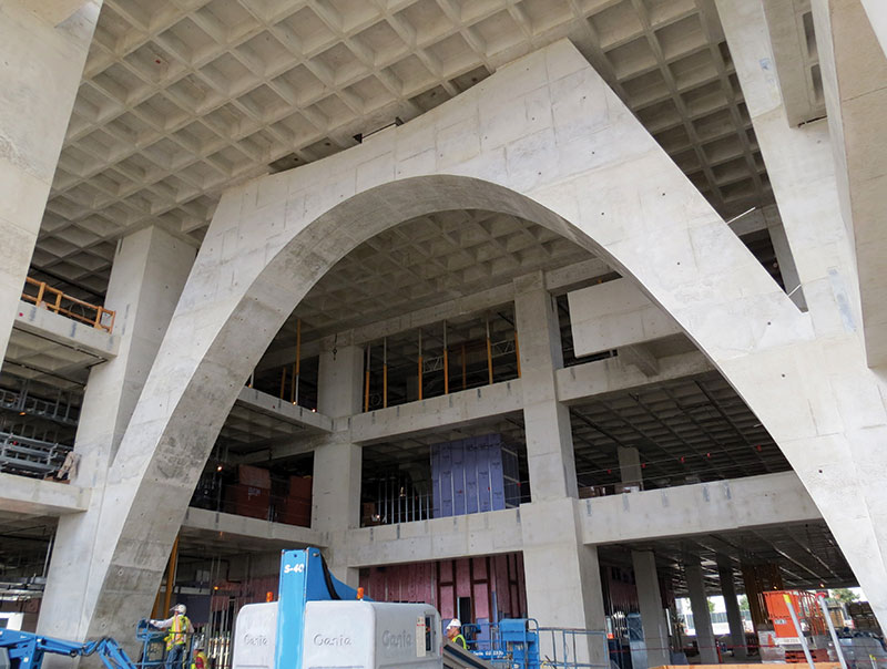
Figure 3: A 64-foot long concrete gravity arch dominates the library’s main lobby.
Concrete Gravity Arch
An open feeling was desired at the library lobby, so a 64-foot (20-meter) long by 46-foot (14-meter) tall concrete gravity arch (Figure 3) was designed from the ground level to the fourth floor, eliminating a column from the center of the lobby. Congestion of reinforcing steel at the two ends where the arch was to be supported by vertical columns proved a challenge. Couplers and headed bars were utilized here and in many other locations where congestion was problematic to constructability.
Reading Room
A concrete roof suspended sixty feet (18 meters) above the eighth floor shelters the library’s 4,000 square foot reading room (Figure 3). Structural steel and clerestory glass supported by four 72-inch square concrete columns complete the room. The concrete columns, cruciform in plan, rise 62 feet to support intersecting concrete roof beams spanning 58 feet in either direction and the diamond-shaped concrete roof slab (Figure 4).

Figure 4: Interior of the 8th floor reading room.
Special Events Room
The Special Events Room roof cantilevers 10 feet from the 9th floor deck and is made up of a hybrid system of precast beams laced into a 6-inch cast-in-place concrete slab. The roof is supported by a single 72-inch x 48-inch inclined concrete column, which begins its rake nearly 90 feet below between the 4th & 5th floors (Figure 4). The flanks of the roof structure are supported in part by tubular steel mullions set prior to casting the roof slab (Figure 5).
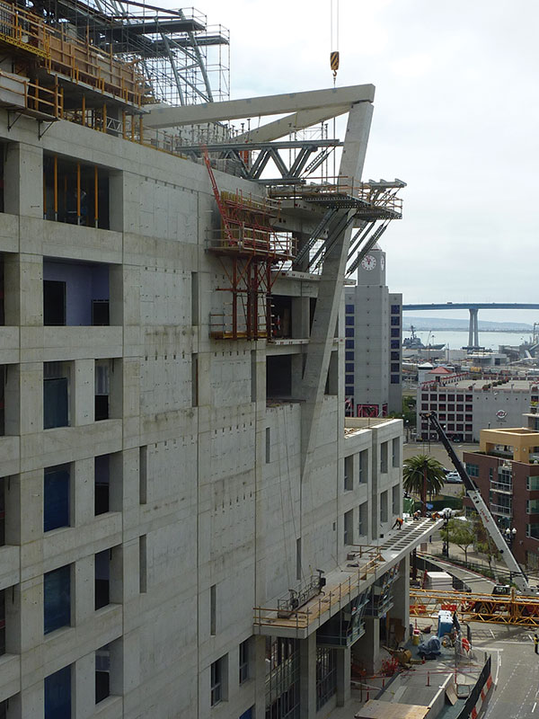
Figure 5: A 90-foot tall inclined column supports a hybrid cast-in-place and precast concrete roof deck at the 9th floor.
Dome
The dome, believed to be the largest steel post tensioned segmental dome in the world, is 140 feet (43 meters) in diameter and rises 221 feet (67 meters) above ground level to provide shade and acclimatize the reading room. It is constructed of more than 3,000 individual members of steel, weighing 285 tons, and clad in 1,500 perforated aluminum panels to shade the eighth floor reading room beneath it. The dome is made up of eight unique truss “ribs” that rise from base to apex in varying heights from 72 to 113 feet (22 to 34 meters) and eight unique “sail” structures located between the ribs.
Sails are oriented in plan with a pinwheel configuration, an effect created by offsetting each of the sails’ vertical leading edges to the outside of the ribs while the sails’ trailing vertical edges are connected to the inside rib surfaces. Each of the sails has an external pipe grid that is spherical at the upper part of the dome; however, the spheres are tipped vertically and horizontally so the center of each sail does not coincide with the center of the dome. Unfurled, the largest sail is 123 feet by 53 feet (38 by 16 meters) wide and comprised of 175 members of tubular steel and 60 cable segments.
Architecturally, the lower edges of the sails are desired to be as thin as possible. This is achieved through the use of a three-dimensional truss spanning diagonally from rib to rib, and appears visually as a six-inch (15 centimeter) edge thickness. To further reduce the mass of the sails, steel cables are introduced to minimize large members on the interior surfaces close to the glass of the reading room. The penultimate concept, with cables covering the outer and inner surface, was deemed too difficult to erect by the contractor. The final design, a saddle shaped cable net, was chosen because the removal of cables on the outer surface allowed the contractor to erect them by crane more easily. The sails were constructed on-site, two at a time, on large temporary platforms on the ground and lifted into place, one sail at a time.
Due to the discontinuous circular form and its peaked pinnacle, the dome behaves as a series of intersecting three hinged arches, or “ribs”. At the base, each rib is supported on a large fixed pin that allows the rib structures to pivot or expand with changes in temperature or seismicity. Each of the eight large pins falls onto one corner of a fixed octagonal plan. The octagonal plan causes unequal geometry from rib to rib. The fixed pins of the rib supports fall onto varying elevations located atop shear walls, freestanding columns and, in one case, supported by three inclined converging columns. Two of the rib supports fall outside the building envelope and are built on special composite braces made up of concrete columns with tubular steel diagonals.
A Place of Inspiration and Learning
The San Diego Central Library is poised to serve its community as a center of knowledge and learning through its planned 1.5 million volumes, internet access terminals, numerous literacy programs, staff, volunteers, and other contributors. The design and construction team believe it will also contribute to the city’s character as an iconic structure and landmark. The expressive and often dramatic applications of architectural concrete and steel discussed here are intended to inspire the minds of the library’s population, be they children or adults, students or working class, rich or poor.▪
Project Team
Owner: City of San Diego
Engineer of Record: Martin & Libby Structural Engineers – San Diego, CA
Dome Engineer: Endrestudio Architecture & Engineering – Emeryville, CA
Design Architect: Rob Wellington Quigley, FAIA – San Diego, CA
Architect of Record: Tucker Sadler Architects – San Diego, CA
General Contractor: Turner Construction – San Diego, CA
Concrete Contractor: Morley Construction – San Diego, CA
Dome Contractor: SME Steel – West Jordan, UT