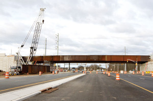
Erecting a Long Single Span Curved Steel Girder Bridge
In 2009, the New Jersey Turnpike Authority began work on a 35 mile widening from Exit 8A to Exit 6 consisting of extending the dualization of the roadway for car and truck lanes. The finished roadway will consist of six (6) lanes in each direction. Five (5) interchanges were reconstructed and/or reconfigured, along with the replacement or widening of all bridges along the route. A total of 23 contracts were let for the project with an approximate cost of $2.5 billion.
Bridge Description
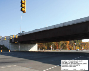
As part of the reconstruction of Interchange 8 in East Windsor, Mercer County, New Jersey, the new Ramp TW/WT needed to cross Route 33. To accomplish this, a new single span bridge was required.
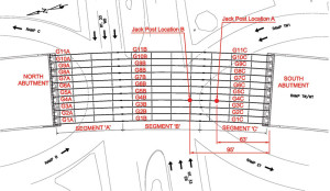
The bridge consists of a simple span superstructure with a cross section of eleven (11) curved steel welded girders spaced at 8 feet 3 inches, supporting a cast in place 8.75-inch deck. Each girder has a web thickness of 7/8-inch and depth of 129 inches. Flange size varies from 26 x 1½ inches to 28 x 3 inches. The span length of the structure is approximately 257 feet 8 inches along its baseline between Girders 5 and 6. The out-to-out width of the bridge deck is 87 feet 10 inches, consisting of an approximate 36-foot wide roadway for eastbound traffic and a 47-foot 6-inch wide roadway for the westbound lanes. The horizontal radii of the girders vary from approximately 1763 feet to 1845 feet, with the abutment bearing lines being radial. Girders 9 through 11 on the outside of the curve have significantly larger flanges than Girders 1 through 8 to accommodate the increased load due to the curvature. Between the girders, cross frames composed of steel angles are spaced at approximately 24 feet (Figures 1 and 3).
Steel Erection Issues
EIC Group LLC (EIC), Fairfield, NJ, was retained by the steel erector subcontractor, Archer Steel Construction (Archer), Manalapan, NJ, to develop the erection plans and procedures for the installation of the steel girders. The erection of this bridge, thought to be the longest single span curved steel bridge east of the Mississippi, presented several engineering and construction challenges:
- The curved girders had to be field spliced requiring the webs to be as plumb as possible for field fit. This necessitated the need for very exact center of gravity calculations and pick point determination.
- Due to the large span length, radius and depth of girder, the stability of the girders both during the pick and at each stage of the erection had to be carefully analyzed and maintained.
- The bridge was constructed above a heavily traveled and active roadway, resulting in very short work windows and lane closure times.
Initial Erection Plan
The steel girders were composed of three (3) segments (A, B and C) spliced together to make up the overall girder length (Figure 3). This long length made the erection of the completely assembled beam as a single lift, either alone or in pairs, not feasible both from a weight and stability point of view. Therefore, the structure had to be constructed by erecting individual segments.
Based on engineering and construction issues over the roadway, it was decided to erect the structure by first erecting one end segment and supporting it on the abutment and towers. Next, the other segments would be assembled on the ground and erected as a unit. This unit would then be spliced in the air to the first erected segment and released.
The southern segment (segment C), approximately 80 feet long, was the only portion of the structure not directly above the active roadway. Therefore, a tower bent was proposed at the location of the B/C splice and then the C segments erected and supported by the South Abutment and the tower bent. It was planned that all eleven (11) towers would be set up, one for each girder line, followed by the erection of all C segments. To satisfy stability requirements, the first 10 segments would be ground assembled and then erected as pairs. The last segment would be lifted as a single and connected to the cross frames from the previously erected pair.
After the C segments were complete, the A/B segments would be ground assembled and then erected as pairs. They would then be air spliced to the C segments and lowered onto the North Abutment. Again, the final girder would be erected as a single.
Typically, for a curved steel girder bridge, it is desirable to erect from the outside of the curve towards the center. As the curved girder is erected, it tends to rotate towards the outside. The result of this rotation is that the web will be slightly out of plumb, but leaning away from the center of curvature and next inner girder to be erected. This outward lean makes it easier for the erector to connect to the cross frames of the next inner girder because the web is facing “up”. After the inner girder is connected to the crossframes, it can then be lowered into place. If the sequence were to go from inside to outside of the radius, then the web would be facing “down” due to the girder roll, and would make it more difficult and time consuming to connect to the next girder. This is especially critical if there is a traffic shutdown and time is of the essence.
However, for single span curved bridges, especially those as long as this structure, this sequence is difficult to achieve. The abutments at each end of the span are constructed radially, thus reducing the opening the erector has to work with when setting each successive girder towards the center. This “pinching” effect will hinder the erector’s ability to swing the girder into place. Because of this and assembly area limitations, Archer needed to erect outward and therefore the roll of the girders had to be precisely controlled. It was planned to set all eleven girders on the towers to control the outward roll so the cross frame connections could be made with minimal effort. Once all girders were erected and plumbed, then all towers would be lowered simultaneously and the structure allowed to assume its deflected position.
The pieces to be lifted ranged in weight from 56,000 pounds for the single C segments to 380,000 pounds for the paired A/B segments. Manitowoc 999 and the American 2250 crawler cranes with capacities of over 200,000 pounds were to be used for the erection. The rigging consisted of a 60-foot segmented pipe spreader beam designed by EIC specifically for Archer Steel, 16-foot pipe spreader cross beams, and wire rope slings with conventional beam clamps. The towers, also specifically designed by EIC for Archer, are 4-legged prefabricated telescoping pipes with steel grillage beams on top. Jacks were specified for elevation control and height adjustment.
Erection
Erection was started in December of 2012. The first four towers were set up beneath segment C for Girders 1 to 4 at their designated locations. Due to availability issues of the remaining towers, it was decided to erect the first four girders in their entirety (all segments) and when complete, the remaining towers would be set up and the last 7 girder lines would be constructed.
Girders 1-4
The C segments of Girders 1 and 2 were then lifted in a pair by the 2250 crane using a pipe spreader and cross beam rigging arrangement, and then walked into position on the south abutment and towers. This was repeated for Girders 3 and 4.
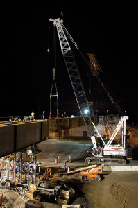
Next, during a complete road closure, the corresponding A/B spliced pairs were lifted and walked using both crawler cranes from the assembly area into an intermediary position in the closed roadway. They were set down on temporary mats while the cranes rotated their tracks into a new position. Once aligned properly, the cranes picked the piece again and crawled forward, air spliced the piece to the C segments and set on the abutment (Figure 2, page 32). This was repeated for the remaining A/B pair. Archer plumbed the girder webs carefully and then connected all cross frames and fully tightened the bolts.
At this point, many of the remaining towers were still unavailable and thus could not be set up as planned. Due to time restrictions, it was decided to lower the towers that were holding G1 to G4. It was expected that the girders would rotate and that there may be difficulty connecting the next outer girder, as now the web would be facing down. To prevent this problem, EIC developed a solution that would utilize supplemental jacking posts under the erected girders while the towers were moved into the new positions.
The proposed solution was to determine the downward deflection that would occur due to the girder roll and then install jacking posts at appropriate locations to jack the 4-girder assembly back up into web vertical position. Then the next 4 girders would be installed and connected to the first 4 girders. The towers would then be lowered again and moved. However, with eight girders in place, it was anticipated that the roll would not be significant enough to affect the erection of the last 3 girders.
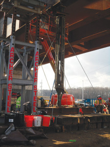
EIC in conjunction with BSDI of Coopersburg, PA performed a 3D finite element analysis of the four and eight girder systems. It was determined that after the towers were removed, the outer girder would drop a maximum of approximately 8.4 inches at midspan with almost 9 inches of lateral outward movement of the top flange. To jack the beams to vertical and remove the deflection, it would have been desirable to place the jacking post at the midspan as this would have resulted in the minimum jacking force. However, due to the active roadway, this was not possible. As a result, EIC decided to utilize two posts, one at 63 feet from the South abutment (Location A) and the other at 95 feet from the South Abutment (Location B) under G4 only. Due to jack stroke limitations, the two posts would work together to allow one jack to be de-pressurized while the other jack was raised to continue jacking. EIC’s analysis revealed that a force of approximately 200 kips would be required at Location A in order to raise the four girders and achieve a plumb web position. For the jacking posts, Acrow Shoring Superprops were utilized supported on timber foundations (Figure 3).
Upon completion of the analysis, the towers were lowered allowing the four girder system to deflect. Measurements revealed deflections and girder roll to be almost exactly as predicted by the 3D model. Next, the jack at Location A was pressurized to lift the girders back to a web plumb position. The load required was also very close to predicted, approximately 200 kips. Also, as predicted by the model, jacking brought the girders fully back to the pre-release position and completely eliminated the girder roll.
While the jacking was occurring at the Superprop, towers were moved and set up under the remaining seven girder lines. An additional three towers became available, so no further intermediate lowering was required. After the remaining girders were erected in similar fashion to the first four, all towers and the Acrow Superprop were lowered simultaneously to allow the fully assembled bridge to deflect downward into its steel dead load only position (Figures 3, 4 and 5).
Conclusion
The erection of single span curved bridges, especially with spans as long as Ramp TW/WT, requires careful planning and analysis to accommodate the large deflections, girder roll, and erection geometry restrictions. However, as typical in most construction projects, sometimes site constraints or issues with material availability require fast, economical and innovative solutions during construction. By performing a rapid and detailed 3D analysis of the partially constructed structure, the Archer/EIC team was able to evaluate the bridge behavior and anticipate response in an unconventional supported position in order to accommodate the contractor’s material availability. The bridge erection was completed within the allotted timeframe with no impact on the overall project schedule.▪
Project Team
Owner: The New Jersey Turnpike Authority
Engineer of Record: Gannett Fleming Inc, Mount Laurel, NJ
General Contractor: Ferreira/Crisdel Joint Venture, Branchburg, NJ
Steel Erector: Archer Steel Construction, Manalapan, NJ
Erection/Construction Engineer: EIC Group LLC, Fairfield, NJ
Steel Fabricator: High Steel Structures, Lancaster, PA
Jacking Post Supplier: Acrow Corporation of America, Parsippany, NJ

