
Malaysia is a country which became independent from the British is 1957 and has been developing its economy and infrastructure ever since. Malaysia is the 3rd largest economy in Southeast Asia and 29th worldwide based upon exports of natural and agricultural resources and petroleum. It has a large manufacturing sector; however, one of the economic goals is to increase tourism. Kuala Terengganu is a city on the eastern side of the Malay Peninsula approximately 500 kilometers (311 miles) Northeast of Kuala Lumpur. This side of the peninsula is less developed and presents opportunity for tourism based upon the beaches and interior habitat. This city of 400,000 is at the mouth of the Terengganu river delta. In order to facilitate economic and tourism growth in the area, a bridge is planned to connect the North and South districts of the city. This bridge will be 672 meters (2200 feet) long with a movable span crossing the navigation channel.
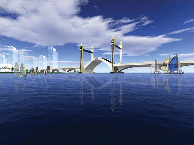
Figure 1. Rendering of the final bridge design concept.
The proposed bridge has pre-stressed concrete approach spans and a twin leaf bascule span over the 50 meter (164-foot) navigation channel. While bridges in the United States are used strictly for transportation, this structure will provide mobility across the river and will also serve as a tourist attraction, allowing viewing of the Monsoon Cup races held locally as a major sporting event. The structure is to serve as an icon of the area and will fit the context of the local architecture.
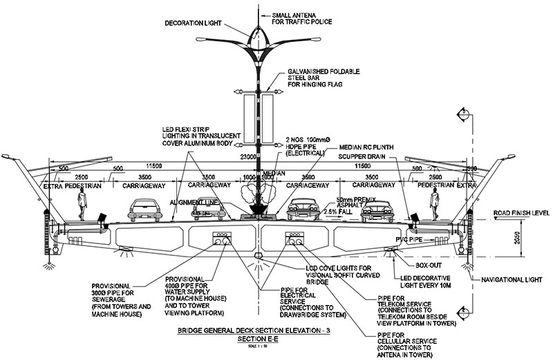
Figure 2. Typical span cross section.
The Bridge
This 672 meter (2200 foot) long bridge carries 4 travel lanes, sidewalks and a median barrier for a width of 23 meters (75.5 feet) (Figure 2). The design speed is 60 KPH (35 MPH) and has a maximum 5% grade. The bridge will have 9 spans plus embankment approaches. Spans 1 and 9 (Figure 3) are designed using concrete beams to provide a minimum under-clearance of 2.2 meters (87 inches) to allow cars to be parked. This parking area will be utilized by the public to both enjoy the waterway as well as access to the amenities at the bridge. Spans 2 thru 4 are pre-stressed concrete box sections of 53 meters (173.9 feet) and 50.5 meters (165.7 feet) in length. These box sections are supported on drilled shafts and cast-in-place piers (Figure 4).
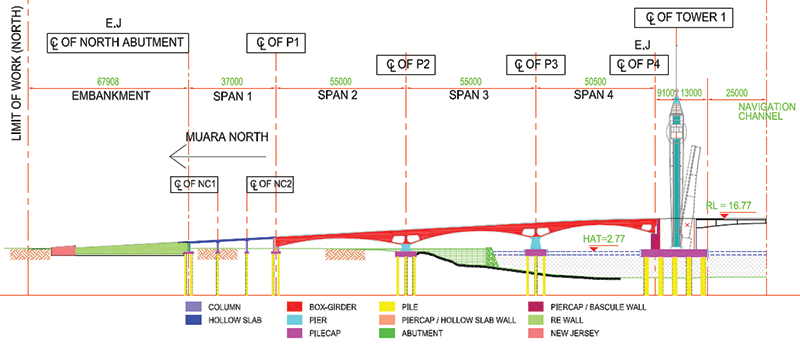
Figure 3. Approach span configuration.
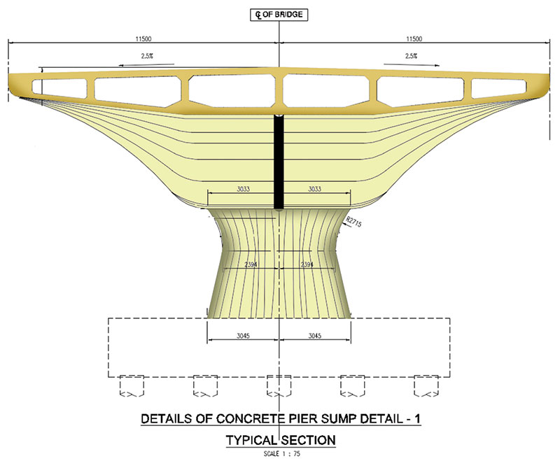
Figure 4. Box sections supported by drilled shafts and cast-in-place piers.
For this structure, there is a high degree of consideration for the aesthetic characteristic to provide a modern image, as well as retain local architectural characteristics.
Movable Span
The movable span provides a 50 meter (164-foot) navigation channel with infinite vertical clearance. The clearance under the bridge when closed is 12 meters (39.4 feet). Contractors in Southeast Asia do not have experience with movable bridge construction. For this reason, it was important to simplify the construction as much as possible while maintaining the required functionality. The bascule leaves will be constructed from steel with a concrete roadway surface. The leaf design utilizes a three girder system for redundancy. Each leaf is 44.9 meters (147 feet) long and is supported by 6 trunnion bearings. The leaves weigh approximately 1600 tonnes each. The trunnions are supported on towers within the enclosed bascule piers. These piers are supported by thirty 1830 mm (72-inch) diameter drilled shafts. Since the alignment of the leaves and machinery is very critical, a decision was made to use hydraulic cylinders to operate the spans. The alignment requirement for these cylinders is more forgiving than for traditional mechanical gearing. Three cylinders per leaf are used allowing for redundancy such that, if a cylinder fails, the bridge will remain operational. Each cylinder has a bore of 458 mm (18 inches) and a stroke of 3390 mm (133.5 inches). When the two leaves are closed, they are locked together with four “lock bars”. These lock bars are high strength steel 254 mm wide and 382 mm high (10- x 15-inch). The bars are driven and pulled using linear actuators. The bridge is controlled by a conventional relay-based system with a computer operator interface. This approach was taken so that a qualified electrician can repair the control system to maintain operation even if the computer-based system fails. The computer system provides both the operator interface as well as a monitoring system for the hydraulic power supplies and the control system function. A programmable decorative lighting system will be installed to highlight both the fixed and movable spans.
Towers
The signature features of the bridge are the towers and the public space created by the connecting structure (Sky Bridge). The towers are 72.5 meters (238 feet) tall not including a 16.6 meters (54.5-foot) antennae. The towers replicate the minarets of mosques and provide a Malaysian version of the Tower Bridge in London. The Sky Bridge public space is 1118 square meters (12,000 square feet) between each pair of towers. Elevators are provided to access the Sky Bridge space as well as stairs for emergency evacuation. The Sky Bridge spaces are two stories, allowing food preparation and HVAC equipment to be located below the public space. Both the North and South approach span roadways have been widened to provide a drop off and loading lane for visitors to the bridge.
Construction
The construction contract for the bridge was awarded in August 2014, with expected completion in 2017. Since the local contractors do not have a history of movable construction, the design team prepared shop drawing level design documents as well as a detailed construction sequencing. The construction sequence will include working sessions with the contractor such that they become aware of the specific challenges of installing, aligning and balancing the bascule leaves. In order for the bascule leaves to be properly aligned, key checks will be performed during their erection. These checks include monitoring deck and counterweight concrete weight, and making adjustments during pouring. In addition, the pouring of the approach span deck will be one of the last items to be constructed so that a smooth transition between the spans is achieved. It is a rare opportunity to participate in such an elegant project.▪