
Poorly defined structural engineering contract scopes rob engineers of time, profit, and – most importantly – the personal satisfaction of their profession. Building Information Modeling (BIM) can improve this challenge if addressed proactively, or compound the difficulties if ignored. The construction industry has reached a point where the use of BIM is not self-explanatory: it could be used to create 2D shop drawings, coordinate trades, or estimate cost. Since BIM came into existence, the industry has lacked a vocabulary for communicating the Level of Development (LOD) between parties. The BIM Forum™ Level of Development (LOD) Specification is an industry-changing reference that enables structural engineers to clarify their scope with BIM, providing the solution to this paramount problem of vague BIM scope definition.
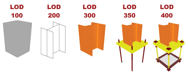
A structural column base plate member at LOD 100 through 400.
Previous to this development, many model element authors were unaware of expectations upon entering a project. The LOD Specification now gives a way to define the scope of detail and input minimums for each particular component of the design. It is simply a collection of definitions describing input and information requirements, and graphic/model examples of the different levels of development for building elements. The document does not outline the necessary levels of development for different steps in the construction process, leaving these determinations for each project team. Instead, it gives a common vocabulary for use between parties on a project team.
LOD Definitions in Terms of Model Elements
- LOD 100 – The Model Element may be graphically represented in the Model with a symbol or other generic representation, but does not satisfy the requirements for LOD 200. Information related to the Model Element (i.e. cost per square foot, tonnage of HVAC, etc.) can be derived from other Model Elements.
- LOD 200 – The Model Element is graphically represented within the Model as a generic system, object, or assembly with approximate quantities, size, shape, location, and orientation. Non-graphic information may also be attached to the Model Element.
- LOD 300 – The Model Element is graphically represented within the Model as a specific system, object or assembly in terms of quantity, size, shape, location, and orientation. Non-graphic information may also be attached to the Model Element.
- LOD 350 – The Model Element is graphically represented within the Model as a specific system, object, or assembly in terms of quantity, size, shape, orientation, and interfaces with other building systems. Non-graphic information may also be attached to the Model Element.
- LOD 400 – The Model Element is graphically represented within the Model as a specific system, object or assembly in terms of size, shape, location, quantity, and orientation with detailing, fabrication, assembly, and installation information. Non-graphic information may also be attached to the Model Element.
- LOD 500 – The Model Element is a field verified representation in terms of size, shape, location, quantity, and orientation. Non-graphic information may also be attached to the Model Elements.
It is important to note that there is no LOD of an entire model; the model is a mixture of different elements within different LODs. Source: BIM Forum™ Level of Development Specification – Draft 2013
Shortcomings and Adjustments
For permit drawings, which will be required for the foreseeable future on building projects, elements are typically only modeled to LOD 300. However, for full trade coordination, higher LOD is required, short of fabrication LOD. For this reason, the author proposed LOD 350 for bridging the gap between element development at permit drawings and fabrication level. LOD 300 does not include the information necessary for full cross trade coordination, while LOD 400 requires information that may not yet be available.
LOD 300 represents model elements traditionally shown in the plan view of a set of construction documents. This would include main structural members, with information such as specific location and type. Construction Documents made from the LOD 300 model are accompanied by 2D information: general notes, typical details, specific details and specifications to define higher level information not typically shown in 1/8-inch scale plans or modeled for permit drawings. For coordination, model elements with an LOD of 350 represent information generally shown with typical details in construction drawings. This information requires trade-knowledgeable input to model accurately. Most main structural member elements are at LOD 300. However, structural engineers must be mindful that LOD 300 requires elements to be in the correct location. For example, although the 2D plans may appear to be correct, sloping roof members that are modeled flat are not at LOD 300. Also, design-level open web bar joists at LOD 300 are not acceptable for trade coordination with MEP, as they do not have the specific manufacturer’s web profiles to detect conflicts. Other areas of misunderstanding are structural elements shared with architecture, such as tilt walls, slabs and load bearing masonry walls. Situations such as this make a compelling case for using LOD 350 as an important step between specific assemblies and detailed assemblies for coordination with manufacturer’s specific content. The structural engineer’s scope should address who is responsible for modeling items such as floor depressions, openings, top of wall heights of parapets, etc.
As more projects require detailed 3D coordination, the need for accurate MEP models will become even clearer to lower the risk of the entire designer team. There is little value in above-ceiling coordination in taking the architectural and structural model elements to LOD 300 (specific in the actual orientation) if MEP model elements are only at LOD 200 (generic in approximate location). Structural engineers should consider adding additional services in their contracts for manual MEP coordination review if the MEP model elements are not to LOD 300. This represents the added time the structural engineer will have to invest in the project during construction administration to deal with changes in the MEP due to lack of model definition (and MEP design). For instance, all gravity plumbing lines must slope for these elements to be at LOD 300, whereas many MEP design models do not slope these lines. This creates the risk of failing to discover that the line will not fit below the structure and above the ceiling if the lines are not modeled at LOD 300 (with slopes). The structural engineer may then be forced to consider adding web openings in their beams or redesigning shallower beams, losing time and profit.
Profit is vital in the business of any profession; structural engineering with BIM is no different. LOD 350 is a key to beating chaos in the design to construction process and aiding structural engineers in the opportunity to find profits in clearly defined project BIM scopes.▪