
By Eytan Solomon P. E., LEED AP, and Richard Lo P. E.
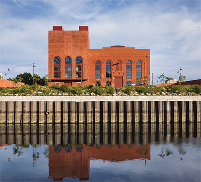
Powerhouse Arts in Brooklyn, New York is a $180 million adaptive reuse project that included extensive renovation and new construction—culminating in 170,000 square feet for fabrication shops, educational facilities, community programs, and multi-functional event space. The project entailed repairing the 55,000 square-foot original steel-and-masonry Turbine Hall, adding a new 3-story, 40,000 square-foot infill structure of cast-in-place concrete within the Turbine Hall volume, and adding a new 6-story 75,000 square-foot Boiler House structure of cast-in-place concrete; all three structures are seismically connected. This article focuses on the history and process of justifying reuse of existing foundations at the site, which was critical to the project.
is a $180 million adaptive reuse project
that included extensive renovation and
new construction.
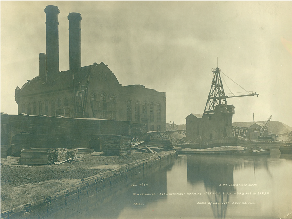
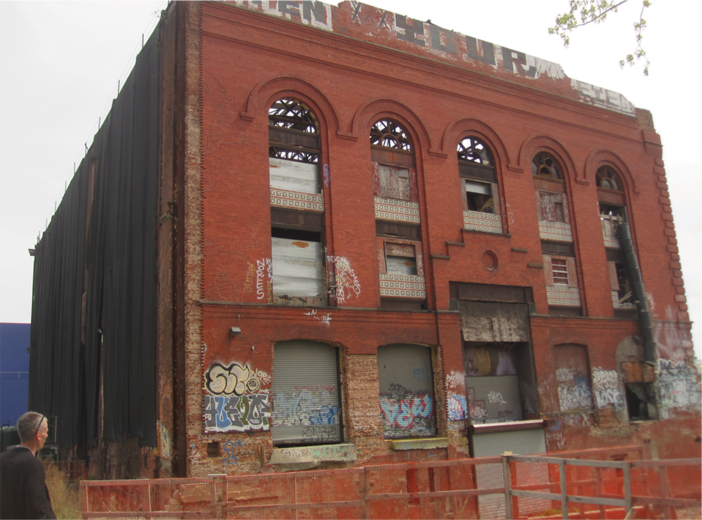
The site, at 322 Third Avenue in Brooklyn, was originally developed and used as a power station for the Brooklyn Rapid Transit (BRT) System. The main original buildings at the site constructed around 1900 were the Turbine Hall and Boiler House, which abutted each other and shared a party wall. The Boiler House superstructure was demolished in the 1950s, while the Turbine Hall (and the party wall) were left in place.
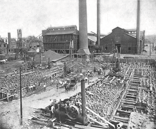
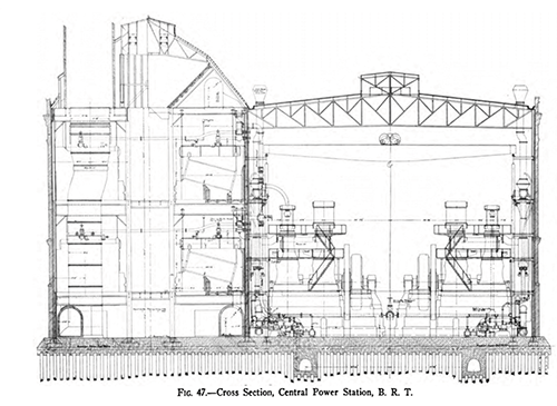
The new project proposed adding back a new Boiler House structure in the footprint of the original and adding a new Turbine Hall infill structure. In deducing from historic drawings, it was believed that the Turbine Hall and the Boiler House were founded on a single monolithic, very thick (6+ feet) concrete mat slab supported by a dense grid of piles.
It was critical to the economic feasibility of the project for these new structural loads to be supported by the existing foundation without significant reinforcement or new deep foundations, due to the extreme soil contamination at the site—being adjacent to the notorious Gowanus Canal. Resulting from the deep thickness of the mat, the groundwater level, and environmental concerns, exploratory probing through the mat to directly load test individual piles was not feasible.
Because the original Boiler House building had been demolished, and no original pile records were located, the governing building code (NYCBC 2014, section 1808.2.7) explicitly limited new loads on such existing piles to no more than half the calculated previous loads on the piles—unless load testing were performed. Half the previous load would have been far too restrictive for the proposed project, therefore the team pursued gross load testing of the piled mat foundation as a system.
NYCBC 2014, 1808.2.7 Use of existing piles. Piles left in place where a structure has been demolished shall not be used for the support of new construction unless the piles are load tested, original installation and testing records are available, or the new loads are no more than half the calculated previous loads on the piles. The engineer shall determine and certify that the piles are sound and meet the requirements of this code.
Silman (the project’s structural engineer) and Langan (the project’s geotechnical engineer) led a campaign to justify the new project loads on the existing foundation, which entailed: structural analysis, geotechnical investigation, foundation grout injection, and load testing, all under ultimate review by the New York City Department of Buildings (NYC DOB) (the Authority Having Jurisdiction) as a CCD-1: “Construction Code Determination”, i.e. a code variance.
Structural Analysis
The existing original Turbine Hall structure—composed of brick masonry walls, steel framing and concrete slabs—exhibited deterioration from water infiltration and vandalism, but showed no discernible signs of damage specifically from foundation settlement. As alluded to below, there was undocumented, non-original construction and backfill present in the building before the current project. Silman calculated the original, existing pre-project, and proposed project loads—for presentation to the team and the NYC DOB.
It was impossible to directly observe the current condition of the mat slab except at very limited exposed areas, and the team did not have information as to whether any settlement occurred when the post-original additional loads i.e., when the Turbine Hall infill structure and topping layers, and the Boiler House soil backfill were added. However, given the estimated existing loads, the inferred former loads, and that the existing original Turbine Hall brick masonry showed no discernible signs of damage specifically from foundation settlement, it seemed reasonably possible to justify a certain amount of load carrying capacity for the existing foundation.
Per discussion with Langan, Silman established the strategy of load testing on top of the existing mat with 1.5 times (per ASTM D1143 reference) the effective additive area load; per discussion with NYC DOB, this safety factor was increased to 2.0.
At the Turbine Hall especially, this load testing would be additionally conservative because the existing infill structure and existing topping slab and soil would also still be in place during the load test. These elements would be removed for the current project construction, but for expediency they were left in place during the load test.
Additionally, Silman calculated an estimate of an individual existing pile’s load based on the historic drawing cross section which showed the existing piles spaced at 2.5 feet each direction. The required capacity per pile (including the loads from the current project) was approximately 10 tons unfactored axial load per pile.
Geotechnical Investigation
While very little original design documentation was available, several historic articles provided clues about the existing foundation. Langan oversaw the execution of 13 conventional site borings, five test pits at the edges of the mat to view the mat and expose a total of eight pile conditions, two groundwater observation wells, and five seismic cone penetration probes. Additionally, ground-penetrating radar (GPR) scanning was conducted by GB Geotechnics across the accessible topside of the mat slab, to locate under-slab voids as much as could be determined with limited non-destructive testing.
With these characteristics of the existing foundations, soils, and voids, Langan performed an analysis of vertical loads on the pile-raft foundation based on a simplified analysis of pile-raft foundations described by Poulous. The method provides an assessment of the overall load-settlement behavior of the foundation where piles are uniformly spaced under a raft (or mat). The method uses the stiffness of individual piles and stiffness of the raft to calculate an overall stiffness of the pile-raft foundation system and estimate load-settlement behavior.
The analysis found that the loads were supported in a shared fashion between the piles and mat as a bearing mat slab: approximately 60% by the piles and 40% by the mat slab bearing. To improve the mat slab bearing and to improve protection of the piles, the team pursued a foundation grout injection campaign prior to the load testing.
Foundation Grout Injection
The cause of under-slab void formation is unknown, but may have been a result of the soft sediments underlying the raft settling over time due to groundwater level changes while the pile supported portion remained in place. The voids were planned to be filled in order to engage the soil subgrade under the piled raft, so that the foundation would be supported by the combined action of shallow bearing and the pile field.
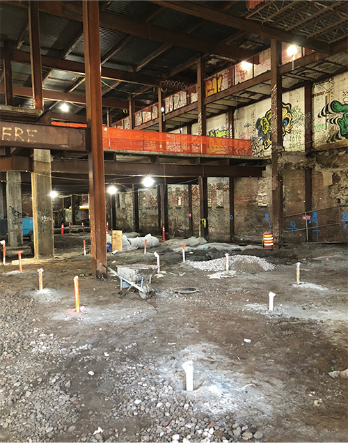
Grout injection ports were installed at approximately 5-foot on center spacing across the full mat slab—both in the Turbine Hall and Boiler Hall—with closer spacing on injection ports in areas suspected to have large voids based on the GPR study, resulting in approximately 1400 port locations. At each location, a 3/4-inch diameter vertical hole was drilled through the mat and probed to physically determine the height of void (if any). If a void was present, a 5/8-inch diameter tubing was installed to the bottom of mat, and the void below was filled with light-weight foamed expansive chemical grout. The grout tube was then removed, and the drill hole was sealed with cement grout.
Load Testing
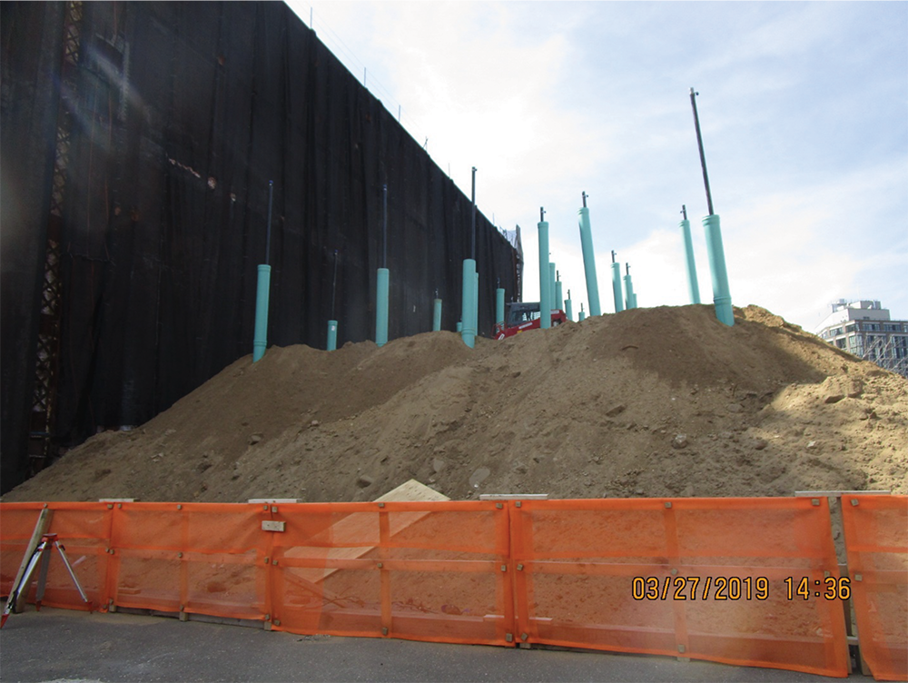
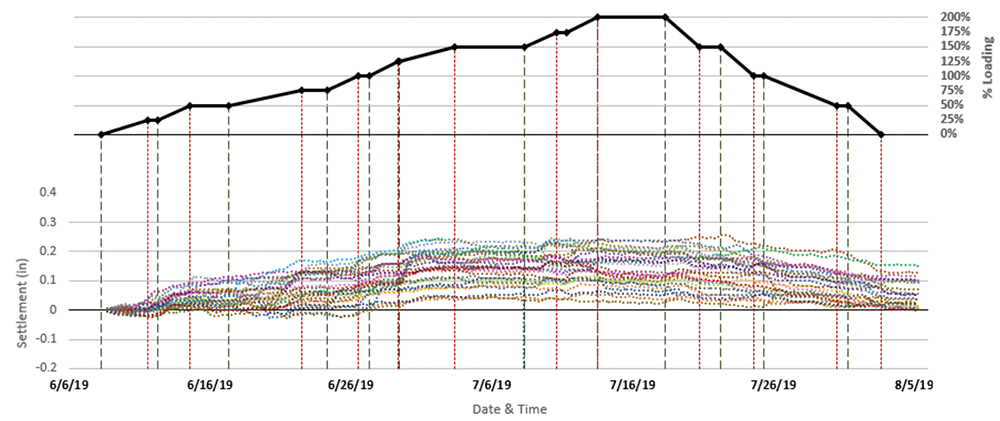
One load test was performed in each of the former Boiler House and Turbine Hall to verify the capacity of the existing foundation and to validate the estimated settlement under the proposed load. The load tests employed soil stockpiles to surcharge large areas and monitored movement of the mat using traditional optical survey. The type of fill used for the stockpiles was monitored to ensure general conformance with the assumed unit density, and consisted of silty sands commonly used as fill in the region.
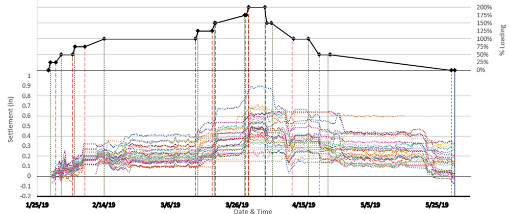
Top of mat foundation settlements were continuously monitored by taking optical survey measurements using an automated motorized total station (AMTS). Survey prisms were mounted to the top of 3-inch diameter steel pipes bolted to the top of the mat. A 12-inch diameter PVC casing was centered on the steel pipes to minimize any disturbances caused by the soil placement. Soil was applied by mechanical means to a series of predetermined heights that corresponded to the increments of a typical pile load test schedule.
The measured settlement behavior for both Boiler House and Turbine Hall loads tests were judged to have been elastic throughout the test load application and correlated well with theoretical estimates. With these encouraging results from the load tests, the rest of the project construction could proceed.
Conclusion
The project would not have been feasible without re-use of the historic abandoned foundations. Creative problem-solving, methodical engineering, collaboration between consultants and the authorities, and a supportive client, were the keys to success. ■
Eytan Solomon, P. E., LEED AP is a Senior Associate at Silman and a member of STRUCTURE’s Editorial Board. (eytan.solomon@silman.com)
Richard Lo, P. E. is a Senior Project Manager at Langan, where he has focused on geostructural interaction, geotechnical engineering, and waterfront structures. He currently leads geotechnical projects in Texas out of Langan’s Austin office. (rlo@langan.com)
References
Poulos, H. G., 2002. Simplified Design Procedure for Piled Raft Foundations. Proceedings of the International Deep Foundations Congress 2002, Orlando, Florida, February 14-16, pp. 441–458.
Roehl, C. E., 1901. The Power Stations and Distribution System of the Brooklyn Rapid Transit Company. Street Railway Journal Vol XVIII, October, New York, pp. 322–332.
Urquhart, 1916. Powerhouse, Coal Hoisting, Machine, Trestle, & Etc. – 3rd Avenue & 3rd St. B. R. T. Insurance Department, September 20.
Murray, Thomas Edward, “Electric Power Plants”, 1910.