
Unique steel moment frame building seismic retrofit benefits from full-scale testing and nonlinear analysis.
In response to increasing concerns about seismic threats in the Bay Area, the owners of San Francisco’s Fox Plaza Tower tackled the challenge head-on. This 30-story structure, constructed in 1966 on the site of the former Fox Theatre, underwent a significant transformation to enhance its performance during a seismic event. This preemptive move was crucial, considering the U.S. Geological Survey’s prediction of a 72% probability of the region experiencing a major earthquake—magnitude 6.7 or higher—within 30 years. This article delves into the remarkable journey of this project. From the comprehensive seismic analyses to the collaborative efforts between industry and academia in full-scale lab testing and the application of an innovative retrofitting scheme, the Fox Plaza Tower has set a precedent in earthquake preparedness for high-rise buildings.
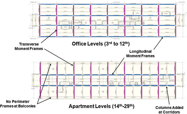
The property on San Francisco’s busy Market Street serves commercial and residential purposes, with offices occupying the 4th to the 12th floors and apartments from the 15th to the 30th floors. The tower’s footprint is rectangular in shape, measuring 75 ft. by 224 ft. The layout of the lateral force resisting system and moment frame connection types differ notably between the upper and lower halves of the building, influenced by differing story heights and clearances for balconies at the apartments. The existing building employs a unique and unconventional lateral force-resisting system consisting of steel moment-resisting frames with haunched beam assemblies. These assemblies incorporate Pre-Northridge welded moment connections, which attach to the strong and weak axes of built-up columns in a space-frame configuration. Most of the beams at the lower levels have a WT section welded to the bottom, extending for approximately one-fourth of the beam’s length from the column face. Notably, there is no lateral bracing at the bottom flange of the beams and WT sections. Reinforced concrete floor slabs are supported by structural steel beams and girders. Figure 1 shows the layout of moment frames at the typical commercial and residential floor levels. Below grade, there is a sizeable two-level parking area that also supports two other buildings. The foundation system utilizes concrete pile caps at the steel columns with 11-in. diameter step-taper Raymond piles that are 56 ft. long.
The analysis of the structure revealed potential damage risks to both the upper and lower sections of the building depending on the nature of seismic events. Therefore, a custom seismic retrofit scheme was developed to counter these threats, which includes strengthening the connections at the upper apartment levels and adding perimeter braced frames with fluid viscous dampers at the lower office levels. The project followed the ASCE 41-13 Seismic Rehabilitation of Existing Buildings standards.
Full-Scale Testing
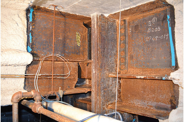
Early in the project, it became apparent that there was no existing research on the behavior of the unique haunched beam-to-column moment connections used in the building. Furthermore, there was minimal data on Pre-Northridge beam-to-column weak axis connections without a haunch. To overcome this, full-scale testing was conducted in the laboratory at the University of California, San Diego, by a group led by Professor Chia-Ming Uang. The ASCE 41 standards recognize the use of experimental data to bridge the gap between the standard specifications and unique, often overlooked, details and characteristics in buildings. This allows for a more precise analysis of structures and ensures the accuracy and reliability of computational models. In this case, the goal of the testing was to understand how these specific connections respond to cyclic loading, with a focus on three types of connections: (a) common beam-to-column weak axis, (b) haunched beam-to-column weak axis, and (c) haunched beam-to-column strong axis. Figure 2 presents an image of a moment frame connection from the project site, showing how the haunched beams are framed into columns in both orthogonal directions. The design team created a laboratory testing program specific to the project, which aimed to predict the performance of these unique connections. The test specimens consisted of a column with a beam framing into one side and utilized the AISC cyclic quasi-static loading sequence, expressed in terms of the inter-story drift ratio. The initial loading phase encompassed six cycles at 0.375%, 0.5%, and 0.75% drift, respectively. Another set of four cycles followed at 1% drift and then continued with two cycles each at progressive levels of 1.5%, 2%, 3%, 4%, and so on. This sequence was followed until the specimen either failed or the test setup was considered to pose a safety risk.
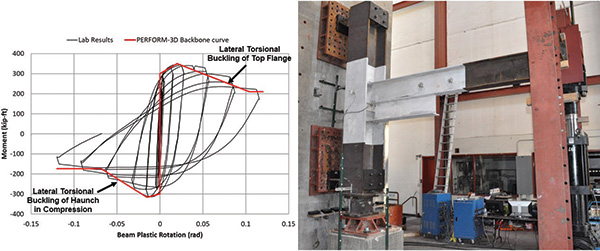
Connections featuring haunched beams generally displayed ductile behavior during tests, without the sudden weld fractures commonly seen in Pre-Northridge connections. However, the introduction of the haunch led to lateral-torsional buckling, resulting in strength and stiffness degradation behavior. This buckling occurred before the full plastic strength of the beam with the WT haunch section could develop. As a result, the vulnerable beam flange welds at the column were safeguarded, but at the cost of reduced strength in the beam-column assembly, which was more than initially expected. The plastic hinging was observed at the tips of the haunches, with no inelastic behavior evident at the face of the columns. Figure 3 depicts the haunched beam-to-column weak axis connection test specimen and the moment versus plastic rotation backbone curve used in the non-linear analysis model.
Seismic Performance Objective and Existing Structure Evaluation
To reduce the risk of collapse during a major seismic event, the building owners had voluntarily undertaken the effort to improve the seismic performance of the existing structure to achieve, at a minimum, Collapse Prevention structural seismic performance at the BSE-1N (475-year) seismic hazard level and to minimize the Life Safety hazard. As such, the design team conducted a detailed performance-based seismic assessment of the existing building using non-linear response history analysis procedures, employing the CSI Perform-3D analysis software. URS Corporation, the project geotechnical engineer, performed a site-specific seismic hazard evaluation for the building site, providing 10 pairs of spectrally matched horizontal ground acceleration records corresponding to a BSE-1N (475-year) earthquake hazard level. These records were then subjected to a 90-degree rotation during the analysis, leading to twenty unique ground motion simulations.
The findings from the analyses showed significant issues in the longitudinal direction of the building due primarily to most of the columns being oriented in the weak axis, with beam-column sub-assemblies exhibiting more severe strength reduction and degradation compared to the transverse direction. In two out of the 20 simulated ground motions, the story drifts in the longitudinal direction exceeded 10%, and the analyses did not converge, suggesting that the building could potentially collapse. Additionally, three other simulated records showed excessive story drift ratios exceeding 4% (beam plastic rotations of 0.03-0.04 radians) in the longitudinal direction.
The transverse building direction did not show any issues with potential collapse as most of the columns were oriented in the strong axis. The frame configuration, moment connection types, and frame member proportioning vary significantly between the upper and lower parts of the structure due to the very different use of the spaces. The non-linear analyses of the existing building revealed that while the upper portion of the structure was vulnerable to certain ground motions, the lower part was susceptible to others. This difference was primarily due to the frequency contents of different ground motions exciting the various higher dynamic modes of the structure. Note that the heavy built-up column splices consisted of welded connections, and hinging of the columns was not observed during the analyses.
Seismic Strengthening Plan
The building’s vulnerability to seismic activity necessitated a retrofit to reduce the risk of collapse and limit excessive deformations. The difference in the dynamic behavior of the upper and lower portions of the building required a hybrid seismic strengthening solution.
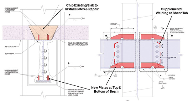
The design team developed a retrofit plan for the upper residential floors in the longitudinal direction to improve the ductility of the beam-to-column weak axis Pre-Northridge moment connections. This retrofit was specifically applied to the connections from the 17th to the 21st floors. The retrofit detail used two pairs of reinforcing ribs welded to the top and bottom beam flanges that provide an alternate load path for tensile forces, effectively reducing the stresses on the vulnerable flange CJP welds. In addition, fillet welds were added between the beam web and the shear tab to strengthen and stiffen the connection. This retrofit strategy aligns with the detail that K-C Tsai and Egor Popov developed and tested to improve the performance of the column weak-axis moment connections at the University of California Berkeley in the late 1980s. Figure 4 illustrates the retrofit detail used for the beam-to-column weak axis connections.
At the lower commercial floors in the longitudinal direction, the excessive drift of the structure resulting from the reduced strength and degradation of the beam-column connections due to lateral torsional buckling could have been addressed by adding lateral bracing to the beams. However, this solution would have been very invasive and could have resulted in issues with the beam flange welds. Although it is not ideal, the lateral torsional buckling behavior of the beam-column assemblies allowed for significant plastic rotation capacity and did not cause substantial strength degradation. As such, two braced frame alternatives were initially considered for retrofit at the lower commercial levels: buckling restrained braces (BRB) and viscous dampers. Although the BRB alternative did result in greater story drift reductions, it also increased the total structural stiffness, consequently leading to higher story shears, which redirected more energy to the upper levels, which increased the story drifts. Furthermore, the BRB option posed substantial challenges for the existing foundation due to the large overturning forces exerted on the columns.
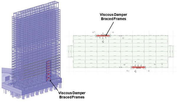
The design team selected the viscous damper option for the lower levels because it offered a more structurally elegant solution. It successfully reduced the story drifts at the lower levels to acceptable levels without adversely affecting the foundation or the upper levels since it does not increase the initial elastic stiffness of the structure. The braced frames with viscous dampers were situated along the two longitudinal faces of the building on the first seven floors above ground, with a total of 14 dampers being utilized. Figure 5 illustrates the viscous damper frame retrofit used at the lower levels.
Since their first use by the space industry in the 1960s, viscous dampers have found wide application in civil engineering. These compact devices, which turn kinetic energy into heat, help reduce stress and deflection in various structures, not just buildings. Due to the precision required in their design, their properties are closely controlled. Before use, each damper is rigorously tested for reliability. Taylor Devices manufactured and tested the dampers used in the project at their plant in Buffalo, New York.
Figure 6 shows the beam-to-column weak axis moment connection retrofit detail and the viscous damper frames during construction. The use of viscous dampers and experimental data for the retrofit design and evaluation necessitated an independent peer review. Accordingly, the design and analysis of the building were peer-reviewed by a team at Simpson Gumpertz & Heger in San Francisco.

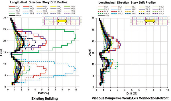
The design team incorporated the inelastic properties of the improved moment connections at the residential levels and the fluid viscous damper frames into the non-linear analysis model of the building, which was used in the evaluation of the overall response of the improved structure and the design and evaluation of the new and existing structural components. Figure 7 compares the inter-story drifts before and after the proposed retrofit scheme and shows that the proposed seismic retrofit scheme will minimize the potential for collapse and significantly reduce the damage potential of the building for the BSE-1N (475-year) earthquake. In addition, beam plastic rotations are kept below 0.02 radians, which ensures that there will not be any severe strength and stiffness degradation at the moment connections.
Plant Construction Company served as the general contractor on the project. The onsite construction spanned approximately ten months and was completed in March 2019.
This project’s unique attributes are as follows:
- The enhancements to the structural system significantly reduce the earthquake-induced story drifts by improving the structure’s energy-dissipating capacity without adding any extra stiffness. Integrating the retrofit solution with the existing building avoided significant additional load on the foundations and other structural elements, striking a delicate balance in addressing the seismic deficiencies present in the two distinct upper and lower halves of the building.
- At the upper residential levels, the beam-to-column weak axis connection strengthening was designed to minimize the impact on the tenants by restricting the construction activity to one floor or even one apartment unit at a time. On average, construction activity within an affected apartment unit lasted only two to three days. The retrofit work impacted less than 5% of the residents at the upper levels at any given time during the construction.
- At the lower office levels, the strategic choice of braced frames with viscous dampers enabled the retrofit work to be confined to just one bay on each side of the building perimeter at the lower levels. As a result, most commercial operations remained functional during the construction.
- The full-scale testing of the building’s unique moment connections filled a knowledge gap, thereby aiding the structural engineering community in gaining a deeper understanding of historic beam-to-column connections in steel moment frames. The project also marked a productive alliance between academia and industry professionals.
- The design and development of the seismic retrofit scheme and the associated peer review process highlight the innovative nature of structural engineering, ensuring that standards keep pace with new developments and the diverse characteristics of existing building structures.