
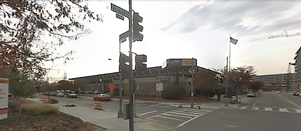
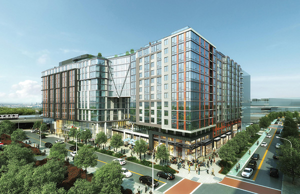
Storey Park, located in the heart of the NoMA (North of Massachusetts Ave) neighborhood in Northeast Washington, D.C., was previously the site of an old Greyhound bus depot lot. Situated near the Metro entrance and adjacent to Union Station, this unique city block of land was ready for redevelopment. With such a large block in a prime location, the development team quickly realized this building would embody the true spirit of mixed-use development (Figure 1).
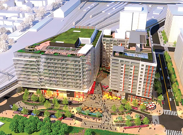
With three levels of below-grade parking, the original design of a U-shaped building could accommodate several uses. Initially programmed for an office building on the west side and apartments on the east side, the building had a natural delineation between these two functions both in façade and floor plate. Needing to look like one building, the ground floor and the roof were at the same elevation; but with office floors requiring more floor-to-floor height, the west office building had two fewer floors than the residential building. Strategically locating columns between the two functions allowed the building to be laterally still tied together without the unnecessary burden of an expansion joint (Figure 2). The design was completed, permitted, and ready to construct with one exception: an office tenant. With prime ground-floor retail and a white-hot residential market, the office tenant was the last piece of the puzzle. As time dragged on and the office market continued to suffer, change was inevitable.
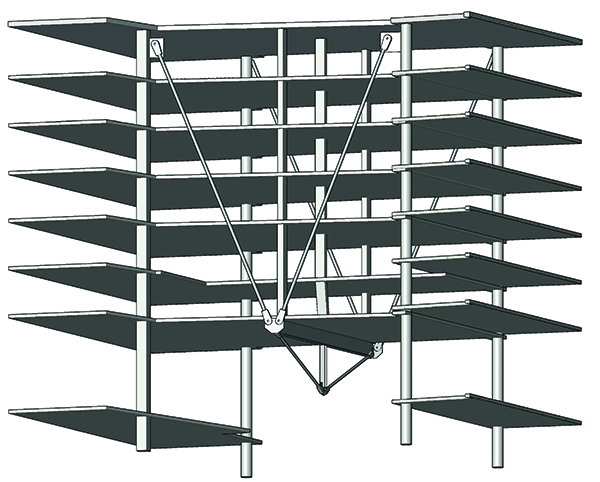
Revising the office to residential space was, unfortunately, not a viable option. The solution was the next best alternative for the area: a flagship hotel. Given the current square footage, a new hotel program would require more space. With the Washington D.C. height restrictions, going vertical was not an option. The only logical option was to connect the U-shaped building and make it donut-shaped. However, due to parking and planning requirements along with other zoning ordinances, only the top seven floors could be connected together. With a span of over 60 feet x 60 feet, floors 7 through 13 would be connected together. The challenge: the area below the new connection needed to be free and clear of columns and other structural framing. Large transfer beams could not be added due to aesthetics, height requirements, and the affect on adjacent rooms/façade. Several options were studied, and eventually, a reverse king post truss with vertical tension rods was determined to be the best option, both structurally and aesthetically (Figure 3).
The Truss
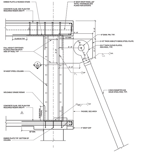
To support floors 7 through 13 with the thinnest slab profile possible, columns would be located within the 60-feet × 60-feet connection. These columns would then transfer the load to the underside of the seventh floor through a reverse king post truss (Figure 4). With such an exposed structural element, the aesthetics of the truss also played an important role. The king post truss comprised a W27×258 top chord that spanned front to back, the two 10-inch diameter solid steel tension rod diagonal members, and the W14×109 hanger post. At the apex where the hanger post connects with the diagonal members,
1 ⅝-inch-thick plates sandwich the members together. These plates provided some out-of-plane and torsional restraint for the hanger post.
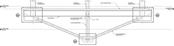
With the high amount of shear in the web members, ½-inch-thick doubler plates were utilized on each end. The concrete columns supporting the floors were strategically located along the top chord members. ½ inch-thick web stiffeners were used due to the high concentration of forces. The vertical end reactions from the reverse king post truss were then transferred back to the supporting building with diagonal tension rods. The tension rods were located at each end of the top chord. With such a large force generated from the floors above, 8-inch-diameter solid rods were used for support. The rods were connected to the truss using 2 ½-inch-thick end plates. Large, specialized clevises were fabricated to connect the ends of the tension rods. The rods continued vertically up, creating a V shape on the front and back of the bridge, and were connected to full building concrete columns at the main roof. With such large tension and shear forces, a W14×257 steel column was embedded into the main building concrete columns at the main roof. These composite columns were connected to the main roof and level 12 diaphragm by an embedded plate with shear studs (Figure 5). To overcome the substantial shear forces, the large embed plates were needed to transfer the load back to the diaphragm.
With multiple floors supported on the king post truss, the analysis of the post-tensioned slabs at levels 7 through 12 was crucial to understanding both the relative short- and long-term deflections of each floor along with the stiffness behavior of the slab. As the king post truss and hanger rods displaced, additional stresses within the slab needed to be accounted for in the design. Using 3D finite element analysis, stresses were reviewed in the slab to determine critical areas needing additional top or bottom reinforcement. Post-tensioning effects were manipulated to account for additional internal stresses.
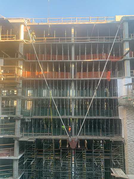
Although the design was documented in the drawings, the construction and erection sequence was a critical piece in the process. Temporary shoring installation and removal below the bridge element was a challenge to the team (Figure 6). This shoring stood 54 ft. from the ground level/second level slabs up to the underside of the seventh floor and supported loads of up to 870 PSF. The shoring needed to support the flat slab above and the complex shape of the king post truss during initial installation, formwork, reinforcement, and placing of concrete. The shoring then needed to be removed in such a way that the four tension rods supporting the truss would be loaded in an identical manner without allowing for any settlement of the slabs or unbalanced loading.
Several options were evaluated to allow for the installation and uniform loading of the rods through a progressive lowering of the shoring towers. However, these options became increasingly complex, leading the team to evaluate the design of the rods. The goal was to find a system that allowed for tensioning of the rods after installation but prior to the removal of the shoring below the 7th-floor slab. The tension rods could not have become engaged until the main roof had been poured and gained the required strength. This made the tension rods unusable for any temporary support.
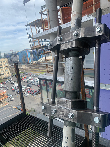
After several discussions and iterations, the plan was to form/reinforce/pour concrete by floor up to the seventh floor. Formwork installation for the seventh floor under the bridge began as the rest of the structure reached the fifth floor so the truss could be set and formed around as the seventh floor structure was placed. The truss was then set, and the seventh floor concrete was placed. The rest of the building above level 7 was placed up to the roof level. The concrete-encased steel columns from the 12th floor to the roof were installed prior to the roof concrete being placed. Formwork was removed between the seventh floor and the roof to allow for the installation of the supporting tension rods. The tension rods were installed and tensioned (Figure 7). Once inspected, the shoring below the bridge was removed. Throughout this process, surveyors performed monitoring on the concrete structure and king post truss to ensure allowable deflection was not exceeded.
Conclusion
Once the initial deflection was determined after the strategic removal of the shoring towers, the façade and waterproofing could then be installed with relative ease. Collaboration between ownership, contractor, architect, structural engineer, and several subcontractors allowed for a creative solution to a unique challenge.■