
Insights into elevating weld designs to achieve successful hollow structural section connections.
By Mike Manor, P.E., MLSE, and Cathleen Jacinto, P.E., S.E.
Hollow structural section (HSS) steel shapes allow for many geometric framing possibilities in structures with the benefit of aesthetic appeal. Maximizing the benefits of HSS sections in a design involves understanding the intricacies of various welding types for connections between members. Several considerations when designing welded HSS connections include the flexibility of the HSS connecting face, corner radius of square and rectangular HSS, and interior access for welding the tube. This article will explore weld selection and design considerations to ensure successful, cost-efficient HSS structures.
Basic Terminology
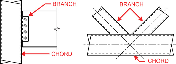
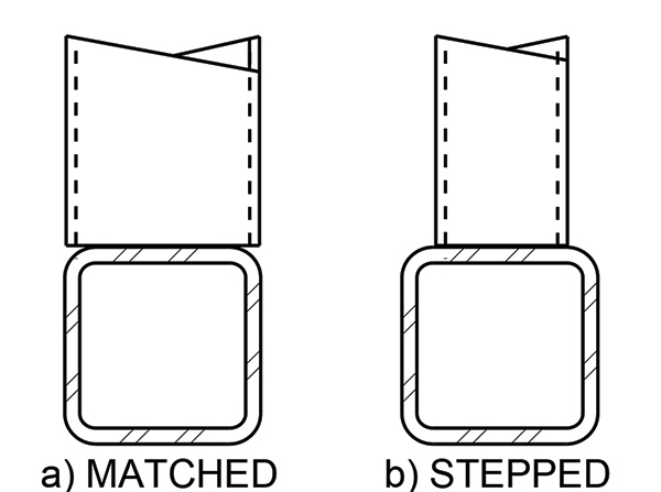
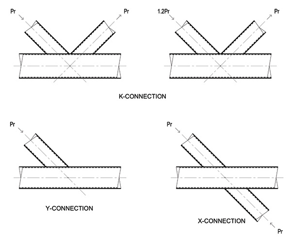
Starting with basic terminology, in HSS connections, there is a single chord plus one or more branches, as shown in Figure 1. The chord is the main supporting member. The branch(es) are the supported elements (plates or HSS, for example) attached to the chord that can impose shear, axial, and/or moment loads to the chord. When two HSS members are connected, they can be in a matched or stepped configuration, as shown in Figure 2. In a matched connection, the branch width is the same as the width of the chord member perpendicular to the chord axis. For stepped connections, the branch is narrower than the chord. Additionally, there are terms for common connection types for plate-to-HSS and HSS-to-HSS connections, as shown in Figure 3. Plate connections are either transverse or longitudinal T- or Cross-Connections. HSS-to-HSS connections are typically T-, Y-, Cross- (X-) or K-connections.
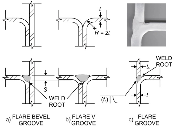
Moving on to weld definitions, HSS connections have various weld types to consider. The strength for all types of welds is based on the effective throat of the weld, which is the minimum distance of the weld cross-section from the weld root to the opposite side. The weld root is the point where the two members being welded are closest together. The first weld type for HSS is a fillet weld, which has a triangular cross-section (AWS 2020). Fillet welds are most commonly used for plates connecting to HSS wall faces as well as for T-, Y-, and K-connections. When the angle between branch and chord is other than 90 degrees, adjustments to the effective throat must be considered per AWS 2020. Two more weld types to be aware of are complete joint penetration welds (CJP) and partial joint penetration welds (PJP). For CJP welds, the weld metal at the root extends all the way through the joint thickness, while for PJP, the weld metal only partially fills the joint. Types of PJP welds for HSS include flare-bevel and flare-V-groove welds. As shown in Figure 4, flare-bevel welds are located between a flat surface, such as a plate or end of the HSS branch, and the curved HSS corner. Flare-V welds occur where two HSS corners are welded together. Usage of these welds as they relate to HSS will be discussed later in this article, but for more in-depth information about weld geometry, strength, installation, and more, see AWS 2020 or AISC Design Guide 21.
Uneven Load Distribution
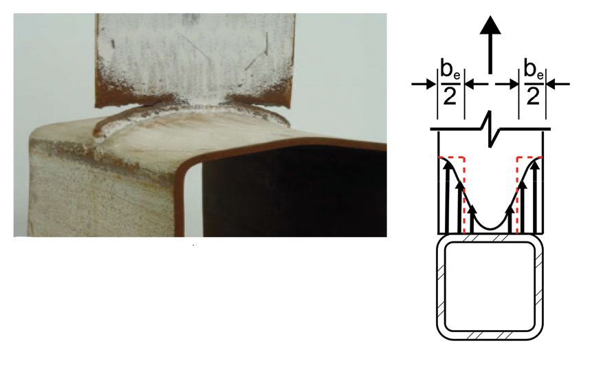
In HSS connections, branch members are often attached to a connecting face of an HSS chord. When the branch is welded transverse to the HSS connecting face and imposes an axial or out-of-plane load normal to the chord wall, the HSS face acts as a plate spanning in its weak direction between the supporting side walls. As demonstrated in Figure 5, the connecting face is stiffer near its sidewall supports and less stiff at its midspan. This results in nonuniform stress distribution across the width of the connecting face. The stiffer portion resists a higher share of the load, and likewise, the load distribution in the weld will follow the plate stress. To account for this, a reduced effective HSS face width is assumed in connection design per AISC 360-22 Specification Equation K1-1. For additional information, see the Steel Tube Institute article: https://steeltubeinstitute.org/resources/understanding-local-yielding-due-to-uneven-load-distribution/.
For square, rectangular, and round HSS, a reduced effective weld length must be considered during weld design. The effective weld length can be calculated per AISC 360-22 Table K5.1 and K5.2. Note that Table K5.2 is new in the 2022 Specification to address round HSS sections.
Figure 5. Uneven load distribution in transverse HSS connections.
HSS Corner Radius
The type of weld used for a connection is influenced by the geometry of the HSS sections in combination with the connection configuration. Due to the manufacturing process, square and rectangular HSS members have a radius in each corner with an allowable variation in tolerance. To account for this range, different radius values are used for geometry in calculations. When determining the workable HSS flat width for stepped connections, the radius is assumed as 2.25tnom per Part 1 of the AISC Steel Manual of Construction 16th Edition. However, for flare-bevel welds in matched connections, an average corner radius of 2t is used (where t is the HSS design wall thickness) per the footnote of AISC 360-22 Table J2.2.
Understanding which corner radius value to use is crucial when specifying flare-bevel groove partial joint penetration (PJP) welds, as the radius determines the weld’s effective throat size and strength capacity. In turn, the radius is based on the HSS thickness (see Figure 4). Hence, HSS thickness is necessary to consider for reasons beyond just the weight and strength of the member. When using AISC 360-22 Table J2.2 to determine weld strength, note that these are the maximum effective throat sizes for flare groove welds. If no effective weld size is specified for a flare-bevel groove weld, the fabricator will typically fill the weld region flush, potentially requiring many weld passes. Therefore, specify the required effective throat size (S) for flare-bevel PJP welds to save cost and reduce welding time. Flare-bevel and flare-V-groove welds can be underfilled as long as the effective throat is specified in the contract documents, with one exception: some categories of Architecturally Exposed Structural Steel (AESS) require that welds be filled flush.
Matched and stepped connection configurations also impact the weld type used. Stepped rectangular HSS-to-HSS and plate-to-HSS connections can generally use fillet welds, while matched HSS-to-HSS rectangular connections require both fillet and the more costly flare-bevel groove welds. Therefore, it is recommended to provide stepped connections instead of matched, where possible, to minimize fabrication costs.
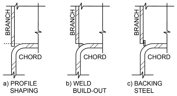
In a matched connection, the weld geometry at the corner radius and root opening varies depending on HSS member size, as shown in Figure 6. This bears greater impact when joining thin branches to thicker chords. The AISC 16th Edition Steel Manual specifies a nominal weld root opening, R, of zero inches, with permissible tolerances of up to 1/16” as detailed and up to 1/8” for fit-up. Should the gap between the chord corner radius and branch wall surpass these limits, available methods to close the root before the final connection weld include profiling the branch to fit around the chord or using steel or weld material for backing. The branch thickness also provides an upper bound limit to the effective throat in flare groove welds (Figure 4c), so HSS thickness must be considered.
Interior Accessibility for HSS
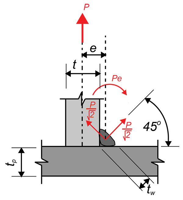
When welding the end of an HSS member to a plate or another HSS, a weld can only be placed on the exterior side of the HSS wall, therefore resulting in a single-sided weld. Some typical locations where this is relevant are in trusses or at column baseplates where the branch is under axial loading. Single-sided welds to tension-loaded HSS members are subject to a local eccentricity, are partially unrestrained from rotation, and are prone to local bending about the weld axis, which can lead to increased stress at the weld root (see Figure 7). Research was conducted on the effects of single-sided welds on HSS, leading to revisions in AISC 360-22 that clarified when the use of the weld directional strength increase factor is appropriate.
Per AISC 360-22, depending on the load angle relative to the weld axis, fillet weld strength can be increased, as noted in AISC Equation J2-5, by a weld directional strength factor, kds. The minimum factor is 1.0 for a longitudinal load parallel to the weld axis with a maximum of 1.5 for a load perpendicular to the weld axis. However, this additional strength is only applicable if strain compatibility of the weld is considered. Thus, single-sided welds at tension members are unable to take advantage of the increase, while double-sided welds can. The weld root opening effect is less significant in round HSS connections due to the curved weld axis, and thus, the directional increase is permitted for round HSS connections. Summarizing, per AISC 360-22 Specification Section J2.4 Commentary and Olson 2020, the weld directional strength increase:
- It is not permitted for rectangular HSS members to base or cap plates in tension (kds=1.0).
- It is permitted for round HSS to base or cap plates in tension.
- It is permitted for HSS members to be connected either to a rigid plate or an HSS chord in compression.
- It is permitted for longitudinal plate-to-HSS connections, assuming welds on both sides in any loading.
- It is permitted for transverse plate-to-HSS connections, assuming welds on both sides and the use of reduced effective weld length per AISC 360-22 Table K5.1 and K5.2, in any loading.
Accessibility also impacts the installation of backing material as required for Complete Joint Penetration (CJP) welds. CJP welds require backing material to ensure sound weld material throughout the weld thickness. If the backing material is not continuous, stress risers can occur with the possibility of premature weld failure at the stress concentration. Without the backing material, the back side of the weld would be exposed to air, which would cause a portion of the weld material to be compromised. It can be difficult and quite costly to install backing along the full length of a CJP weld in closed sections, especially at the corners of rectangular HSS. The backing material must be carefully sized and installed for continuity around the entire interior HSS perimeter, and then be welded in place along the inside edge of the tube. This can be labor-intensive work necessary to prepare for a CJP weld. Once the CJP weld is complete, there is another complication. For static and wind loads, the backing material can remain in place for the life of the structure. However, portions of the seismic design code require the removal of backing bars in seismic connections after the weld is complete such as column to baseplate connections among others. AISC 341 and AWS D1.8 provide specific information on when backing removal is required. For an HSS member, backing on the inside is not accessible for removal. Challenges related to backing material are one reason why CJP welds should not be the default weld for HSS connections. In the following sections, we will further explore HSS considerations for various weld types, including a discussion on alternatives to CJP welds.
HSS Fillet Welds
Fillet welds are the easiest type of weld for both designers and welders to work with and are great for stepped HSS connections. Access is limited to only one side of HSS walls at connections, and, as a result, the leg size of the fillet can often exceed the thickness of the HSS member being connected. (Note that AISC 360-22 Section J2.2b, in referring to maximum weld sizes at the end edge of the steel member, does not apply to fillet welds at matched or stepped connections).
When calculating the strength of fillet weld connections, the strength of both the fillet weld material and the base material must be checked with the lowest value controlling the capacity of the joint. For HSS, the ASTM A500 material available in the current marketplace is either grade C or dual graded for both B and C. Looking at AISC Design Guide 24 1st Edition Table 2-2, the calculations demonstrate that the base metal rupture limit state for ASTM A500 Grade C material governs over yielding. Tables 2-2 and 2-3 of the Design Guide aid in verifying the HSS wall thickness is adequate to transfer the shear along the weld. Note that in 2022, there were updates to ASTM A500, revising the Fy and Fu values to be 50ksi and 62ksi, respectively, for both round and rectangular HSS. Updates for a second edition of AISC Design Guide 24 are underway, which include a weld table revision to reflect the current values but are not yet available as of this writing.
When designing fillet welds, consider the number of weld passes required for installation and only specify the weld size required to meet the load demand. The larger the fillet weld, the more welding passes it takes to complete the weld. Per AISC 16th Edition Manual Table 8-12, a single pass is adequate for welds up to 5/16” with the number of passes increasing quickly for larger weld sizes. Factoring the number of weld passes and the bevel preparation required for groove welds, fillet welds up to ¾”are generally more economical than groove welds.
HSS Partial Joint Penetration (PJP) Welds
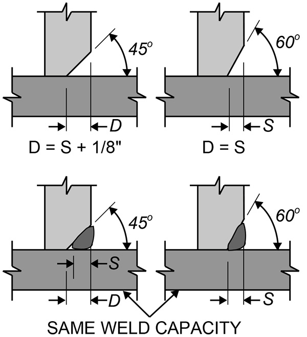
PJP weld strengths are calculated per AISC 360-22 Table J2.5 with effective throat (S) per Tables J2.1 for bevel groove welds and J2.2 for flare groove welds. These effective throats are also graphically shown in AISC 16th Edition Manual Table 8-2. You can see in Figure 8 that different welding processes can be used, resulting in the same effective throat and capacity. Thus, it is recommended for PJP welds to call out the required (S) in the weld symbol (include the parenthesis to indicate this as the effective throat) to allow the fabricator to determine the best welding process for the project. Designers should also ensure rotation about the root of PJP welds cannot occur.
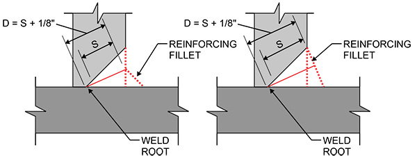
Occasionally, a PJP weld may not have sufficient capacity to meet the load requirements. If it is not possible to revise the connection geometry to increase the effective throat, then there is still another option to consider before specifying a much more costly CJP weld. A reinforcing fillet weld can be added to a PJP weld to increase the effective throat (S). Figure 9 shows images demonstrating the effective throat for PJP welds reinforced with fillets which can be compared to Figure 8 for a PJP alone. Notice that when reinforcing the PJP, the capacity is NOT equal to the sum of the two weld capacities. Instead, the welding capacity is determined based on the effective throat of the combined weld, which is the shortest distance from the joint root to the weld face of the diagrammatic weld minus any applicable groove weld reductions. To specify fillet reinforcement, see AISC 16th Edition Manual Table 8-2 for the pertinent prequalified PJP weld sketch.
HSS Complete Joint Penetration (CJP) Welds
CJP welds are often specified when a non-bolted option is desired in connecting two HSS members. However, they are the highest-cost weld to specify and are often overkill. Besides requiring a significant amount of time to complete the weld, CJP welds trigger additional installation and inspection requirements. All CJP welds require special inspections both prior to and after the welding process and some configurations require additional weld certifications. As discussed earlier, CJP welds also require backing material, which can be a challenge to install in closed sections.
Therefore, the recommendation is to leave CJP as the last option. There are only rare occasions where CJP welds are required such as specific categories of AESS in high seismic applications. A common misconception is that CJP welds are better than PJPs for a variety of reasons, but this holds true primarily for fatigue-loading conditions. While CJPs fully develop the HSS wall strength in the connection, the reality is that PJP welds can also fully develop the HSS wall strength but without all the extra hassle of backing bars and inspection. Specifying the required effective weld size (PJP weld) rather than leaving the weld symbol blank (CJP weld) can go a long way toward the achievement of an economical connection. Also, specifying a fillet-reinforced PJP weld (Figure 9) is a great alternative to a CJP weld. For more information, see the Steel Tube Institute article: https://steeltubeinstitute.org/resources/cjp-hss-welds-be-informed-before-you-specify/.
Conclusion
The design and selection of welded connections for Hollow Structural Steel (HSS) sections are crucial for achieving successful and cost-efficient HSS structures. Understanding key factors such as the flexibility of the HSS connecting face, the corner radius geometry of square and rectangular HSS, and the challenges of weld accessibility inside the tube is essential. Additionally, the amount of work required to perform the various types of welds will greatly impact the cost of HSS connections. Fillet welds are a cost-effective choice for many HSS connections, but engineers must carefully assess the size and number of weld passes required. PJP welds provide versatility and can be reinforced with fillets if needed. While CJP welds offer a quick easy design, they come with added complexity, cost, and inspection requirements, making them a last resort. The choice of weld type should align with project requirements while minimizing unnecessary expenses. A thoughtful approach to weld design, considering HSS geometry, loading conditions, and cost efficiency, can lead to the successful realization of aesthetically appealing and structurally sound HSS structures. For additional HSS design guidance and resources, visit the Steel Tube Institute website: https://steeltubeinstitute.org.
Mike Manor and Cathleen Jacinto serve as HSS Technical Consultants to the Steel Tube Institute and are practicing Structural Engineers with FORSE Consulting. (hssinfo@steeltubeinstitute.org).
References:
- AISC, 2022. “Specification for Structural Steel Buildings,” ANSI/AISC 360-22, and Commentary, American Institute of Steel Construction, Chicago, IL.
- AISC, 2023. “Steel Construction Manual, Sixteenth Edition,” American Institute of Steel Construction, Chicago, IL.
- AWS, 2020. “Structural Welding Code – Steel,” AWS D1.1/D1.1M:2020, American Welding Society, Miami, FL.
- Miller, D. 2017. “AISC Design Guide 21 Welded Connections – A Primer for Engineers Second Edition,” American Institute of Steel Construction, Chicago, IL.
- Olson, K. 2020. “CJP HSS Welds: Be Informed Before You Specify,” Steel Tube Institute.
- Olson, K. 2020. “Directionality increase for Fillet Welds to HSS,” Steel Tube Institute.
- Packer, J. 2017. “Weld Effective Lengths for Round HSS Connections,” Steel Tube Institute.
- Packer, J. 2022. “Welding in HSS Corners,” Steel Tube Institute.
- Packer, J., McFadden, M. 2012. “Welding of Hollow Structural Sections,” Steel Tube Institute.
- Packer, J., Sun, M. 2015. “Design of Fillet Welds to Rectangular HSS,” Steel Tube Institute.
- STI, 2021. “HSS Design Manual, Volume 1: Section Properties & Design Information,” Steel Tube Institute.