
The repurposing of One Milk Street, Boston
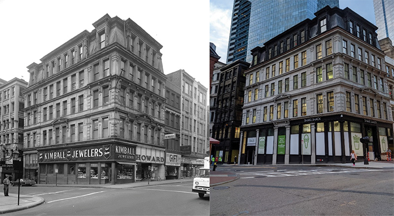
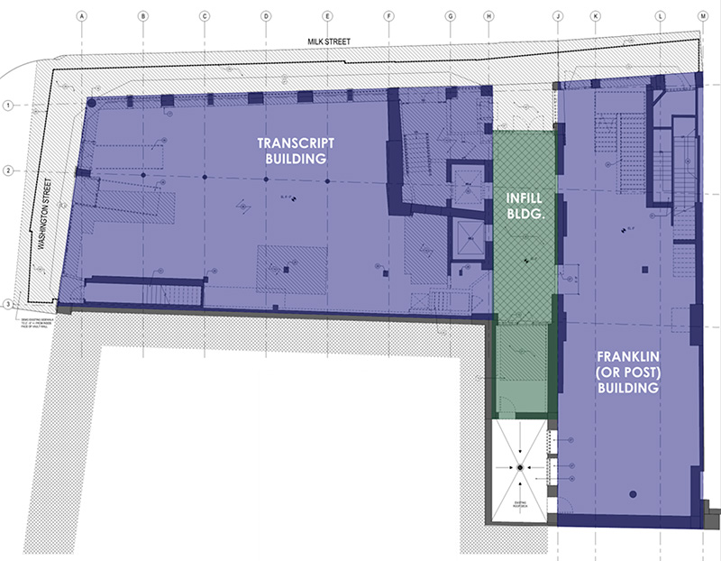
Located in Boston’s Historic Newspaper Row District and at the location of Benjamin Franklin’s birth, One Milk Street is composed of three connected buildings: the Boston Transcript Building (circa 1873), the Boston Post Building (circa 1874), and a reinforced concrete connector building from the 1930s (Figures 1 and 2). These three buildings, as with many mass masonry and timber buildings of this age, have had numerous modifications over their 100+ years. The current rehabilitation project encompassed a full building renovation with structural alterations to create mixed-use upper-floor offices and retail space on the ground floor. As Engineer of Record (EOR) for the renovations, Simpson Gumpertz & Heger (SGH) performed a broad range of scope including, but not limited to, evaluation of the existing structural components of the building to determine the level of code-triggered structural upgrades; development of a procedure for in-situ proof load testing of the existing heavy timber floors; and design of new structural components such as new elevator cores, egress stairs, a two-story mechanical penthouse, a new entrance canopy, and new concrete sidewalk vaults. This multifaceted project highlights the challenges inherent in structurally retrofitting 19th-century buildings.
Project Overview
While medium-scale in square footage, the project saw large-scale challenges both from existing conditions as well as scope changes during design and construction. SGH first visited the building in June 2015 and was involved in the final tenant fit-out in Fall 2020; throughout SGH as EOR provided project continuity for building owner Midwood Investment and Development (Midwood) as the project team saw substitutions for both the project architect firm and general contractor. The long timeline highlights the challenges and design iterations encountered as the team progressed from the feasibility stage to the immediate repairs and floor upgrades phase, followed by the base building retrofit and final tenant fit-out.
In 2015, the project team envisioned a building retrofit focused on mechanical system upgrades with limited structural modifications. SGH’s preliminary scope included the following:
- Structural International Existing Building Code (IEBC) Feasibility Study
- Building Façade and Roofing Visual Survey
- New 6-Story Elevator Shaft
- New Multi-Story Rooftop Penthouse
- New Rooftop Mechanical Dunnage
- New 2-Story Basement Elevator
- New Retail Stairs
- New Entrance Canopy
- Miscellaneous Mechanical Penetrations
- New Retail Entrance Ramp
- By the end of construction, SGH’s scope had expanded to also include:
- Structural Replacement of Sidewalk Vaults
- Removal of the Existing Basement Mezzanine Floor
- Structural Evaluation of Existing Floor Structures
- Development of an On-Site Adhesive Anchor Testing Program
- Visual Survey, Timber Grading, and Strengthening of the Existing Roof Structure
- In-Situ Load Testing of Existing Timber Floors
- Removal of an Existing Basement Column
- Visual Survey of Existing Mass Masonry Elevator Shafts and Bearing Walls
- Extensive Engineering Support for owner, contractor, and design team throughout construction
This article focuses on four of the major scope items associated with the project: the structural feasibility study, the removal of an existing basement column, the replacement of existing deteriorated sidewalk vaults, and the in-situ load testing of existing timber floors.
Feasibility Study
SGH was brought onto the project by Architect #1 to conduct a feasibility study of the renovation. Given owner budget constraints, Architect #1 sought to renovate the building within the limitations of the existing building structure (i.e., limit the extent of structural modifications, focus on updating architectural finishes, improve stair and elevator access, and upgrade mechanical systems). SGH’s 2015 feasibility report stressed that structural modifications should be limited in scope to avoid triggering a building-wide structural seismic evaluation for current building code loads required by the IEBC for substantial structural modifications encompassing more than 30% of the building structure. Given the age of the building, SGH noted that major seismic upgrades would be required if the design team triggered the IEBC requirement.
After a 6-month pause, SGH was contacted by Architect #2, who took over the project and proposed an expanded scope to meet the owner’s needs. In feasibility study #2, SGH used visual plan markups to illustrate how proposed scope changes triggered substantial structural modifications and code-required seismic upgrades. These markups enabled the project team to refine a project scope that met the owner’s expectations without triggering substantial seismic upgrades.
Column Removal
The owner desired a new 2-story basement elevator to connect the double-height basement space (after the removal of an existing basement mezzanine level) with the ground floor retail space of the Transcript Building (Figure 3). Given the tight existing building layout and required egress paths on both floors, the architect could only place the new elevator at an existing building column location. This column supported all building levels. SGH was tasked with developing a solution that allowed for the elevator shaft to be installed while also supporting the existing building above.
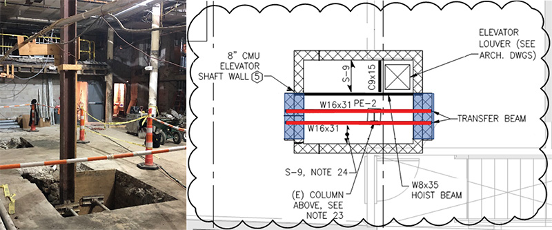
SGH designed the reinforced CMU elevator shaft as the new “column” of the building. Steel transfer beams at the top of the shaft (Figure 3) transfer load from the existing steel column above to the shaft walls. A new reinforced concrete mat foundation/pit supports the full structure above.
However, two challenges arose from this approach: the transfer of existing load from the existing column to the new shaft and the design of the new mat foundation. Both issues highlight the need for collaboration between the EOR’s final design and the General Contractor (GC)’s construction means and methods.
First, SGH specified the GC to submit a shoring and jacking sequence for the demolition of the existing column and construction of a new shaft. While SGH had designed the shaft to support the building loads in the final design condition, the transfer of loads from the old to the new structure needed to be an engineered sequence designed by the contractor. The GC’s scaffolding subcontractor initially proposed two scaffolding towers be constructed on either side of the proposed elevator, with transfer beams supporting the existing column above at Level 2. Under this sequencing, the GC would construct the temporary scaffolding towers with transfer beams, connect the transfer beams to the existing column, cut and remove the existing column and foundation, and then construct the new foundation and CMU shaft up tight to the steel transfer beams.
SGH stressed that the contractor’s sequencing did not provide a controlled transfer of loads from the existing column into the transfer beams. Since building forces already existed within the column, the GC needed to jack the load into the transfer beams prior to cutting the existing column. Simply cutting the column without jacking would risk an uncontrolled, unsafe transfer of load between the column and the beams. Furthermore, the proximity of scaffolding towers to the new pit excavation would undermine the scaffolding.
Given the constrained floor plan around the proposed elevator, SGH worked with the GC and the shoring contractor to develop a solution to switch out the existing column for the new masonry shaft while maintaining the building’s structural load path. The team’s solution was to use the shaft itself as the column shoring prior to the column’s removal. Specifically, the sequence entailed:
- Excavating the proposed elevator pit around the existing column footing
- Doweling the new elevator foundation to the existing column footing to allow the new CMU shaft to be erected with the existing column in place
- Attaching steel transfer beams to the existing steel column at Level 2
- Erecting the masonry shaft
- Erecting scaffolding within the shaft to allow for the load jacking sequence
- Jacking the existing building load out of the column and into the transfer beams
- Shimming the top of the CMU walls tight to the transfer beams
- Releasing the jacks to transfer the load into the CMU shaft
- Demolishing the existing steel column from within the elevator shaft
Sidewalk Vaults
Basement vaults below city sidewalks are common in older cities like Boston. However, poorly maintained vault structures can pose a risk to pedestrians if no condition assessment is performed and water ingress is a factor.
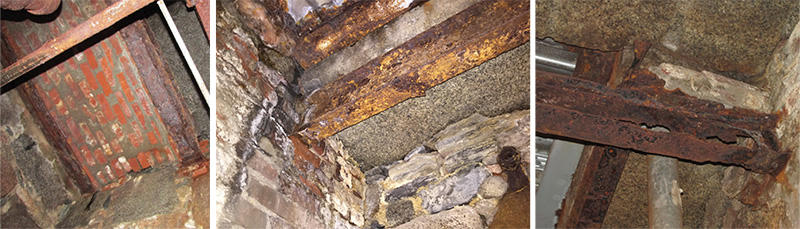
One Milk proved to be one such case study. SGH’s initial survey found sidewalk structural conditions ranging from original granite stone slabs supported on heavily corroded steel to brick masonry arches, previous concrete on metal deck repairs, and exterior stone foundation walls (Figure 4). The city historical commission required that the original granite slabs remain in place, while the city building official noted that the sidewalks must support an equivalent H20 truck wheel load (16 kips per AASHTO).
The team initially sought to repair and rehabilitate the sidewalk in place with retrofit work from the basement vault below. The contractor would install new steel framing to support existing granite slabs while also repairing and sealing cracks. This scheme sought to minimize disruption at the street level, manage construction costs, and retain the historic character of the original sidewalk.
However, this scheme could only mitigate rather than prevent future water ingress and would require ongoing maintenance. In addition, it would require significant structural steel for new loads and still leave the owner with a patchwork sidewalk. The GC separately advised repairing the sidewalk at street level, as getting new steel into the tight basement vaults would be difficult and costly.
SGH and the team subsequently developed a topside sidewalk replacement where existing granite slabs were removed, and a new reinforced concrete structural slab was cast to span between existing stone foundations at the street and new steel framing at the building face. The architect used the new concrete slab as a clean substrate for a waterproofing layer. To meet the historical commission requirements, ,which focused only on maintaining the original granite visual, the original large granite slabs were shipped off-site, cut, and reinstalled as a wide curb on top of the new concrete slab, while a layer of high-strength rigid foam and a non-structural concrete topping was installed to provide a top walking surface.
In-Situ Floor Testing
The building’s ground floor level was classified for existing retail (one hundred psf occupancy load) with a mixture of structural systems (concrete on a metal deck, corrugated metal arches supporting concrete, and brick masonry arches). The upper floors were classified for existing office space (50 psf occupancy load) and were composed primarily of heavy timber framing. The design team intended for the upper floors to remain office space. To lease the space, Midwood sought to install a cementitious topping on the floors to meet flatness and levelness requirements for a floor finish substrate. In spring 2017, Midwood had SGH structurally evaluate existing floors for an additional standard one-inch-thick cementitious floor material.
However, in late 2018, an independent survey of the existing upper floors by the prospective tenant determined that the original floors were out of tolerance for flatness and levelness by as much as four inches. The tenant, therefore, required thicker floor prep material to support their proposed finishes, resulting in a higher design load. With new ceiling finishes already installed in the building, Midwood asked SGH what the team could do to meet the tenant’s loading and levelness requirements, keep the lease on track, and avoid replacing all the completed upper-level floors. Due to newly installed ceiling finishes, SGH could not survey the wood floor structure. Therefore, SGH recommended on-site proof load testing of the floors to evaluate the timber floor’s reserve capacity.
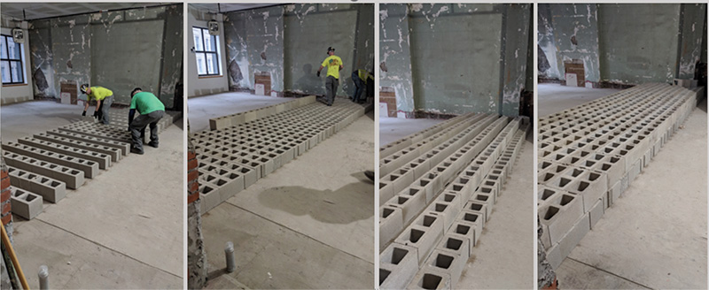
Using Section 1708 of the 2015 IBC along with ASTM E196-06 (Standard Practice for Gravity Load Testing of Floors and Low Slope Roofs), SGH developed a testing procedure for the wood-framed upper floors. A representative floor area was designated on Level 5 of both the Transcript Building and the Post Building. To avoid damaging newly installed finishes, the team elected to use standard CMU blocks instead of typical water-filled drums for the test weights. The contractor removed ceiling finishes from the representative test areas, allowing SGH to conduct a wood microscopy analysis and in-situ visual stress grading.
The SGH-developed testing procedure entailed:
- The GC incrementally added CMU block to the floor in four increments (Figure 5)
- The SGH and surveying team measured floor deflection on the floor below for each load increment. Loading was halted for 1 hour before the addition of the next CMU increment
- The team left the fully loaded floor in place for 24 hours to monitor deflections due to creep
- After the 24-hour loading period, the contractor incrementally removed the CMU
- The team measured floor deflection rebound after each unloading stage with a 1-hour wait between increments
- The team monitored the unloaded floor for another 24-hour period to measure floor deflection rebounding
The team determined that both test areas met the IBC deflection and recovery criteria for a successful test and could support an additional load of ninety-two psf, satisfying the tenant requirements and allowing Midwood to proceed with their tenant lease agreement.
Through collaboration, the design team was able to preserve major portions of the historic character, façade, and structure of the building while also integrating modern egress paths, retail businesses, and office space. As EOR, SGH was able to provide continuity on the project team for the owner and help Midwood understand the multiple structural systems in the building. SGH, the architect, and the GC were then able to navigate the challenges of these varying existing building conditions to integrate new structural components and load-test existing floors to keep the project moving toward successful completion.■