
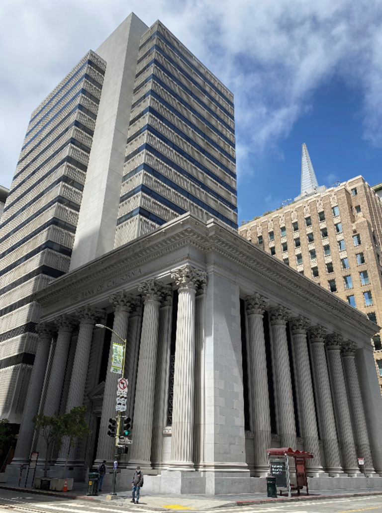
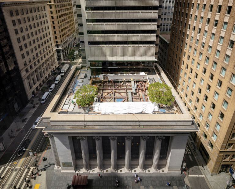
Built among the rubble of the 1906 San Francisco earthquake, The Bank of California Banking Hall, located at 400 California Street, was among the first commercial buildings to be completed following the 7.9 magnitude quake – the deadliest natural disaster in California’s history. Constructed of steel, concrete, and granite, plans for the Banking Hall at 400 California Street had been completed before the quake, allowing it to be a keystone of the rebirth of the financial district. Almost 60 years later, the new Bank of California headquarters was built directly adjacent to the Banking Hall. Located at 430 California Street, the new headquarters building (the Tower) is a modern, 21-story steel-and-concrete high-rise tower, structurally separated but functionally connected to the Banking Hall.
On the afternoon of October 17, 1989, California shook once again. Originating from the San Andreas fault with an epicenter approximately 70 miles south of San Francisco, the 6.9 magnitude Loma Prieta earthquake caused substantial damage throughout the greater San Francisco Bay Area. Among the buildings damaged, large cracks emerged in one of the corner piers of the Banking Hall. While the Tower did not show any signs of damage, it was believed that damage to the Banking Hall resulted from the two buildings colliding during the quake.
The sale of the two buildings in 2016 set in motion a series of renovations and improvements for new tenant occupancy. With full-building tenants moving in, the non-structural alteration provisions in the San Francisco Existing Building Code triggered a seismic evaluation of the Tower. While not required by code, the team performed a seismic evaluation of the Banking Hall – building number three on the city’s list of designated landmarks – due to its functional connection and close adjacency to the Tower. The evaluation also achieved the owner’s interest in understanding the seismic performance of the historic Banking Hall.
San Francisco Existing Building Code provisions allowed the use of ASCE 41-17 Seismic Evaluation and Retrofit of Existing Buildings as the basis of the seismic evaluation. The design team worked with the Owner and the San Francisco Department of Building Inspection (SFDBI) to establish the ASCE 41-17 seismic performance objective for the two buildings at Life-Safety under the BSE-1E seismic hazard.
400 California Street – Historic Banking Hall
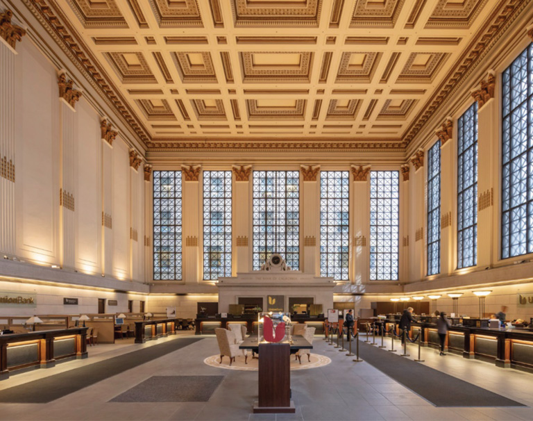
The Banking Hall has plan dimensions of 124 feet by 84 feet and has a single-story roof height of 62 feet and a basement below. At the roof level is a terrace, constructed in 1965, consisting of concrete fill on metal deck over steel framing and is accessed from the 5th floor of the Tower. The 1908-era concrete roof slab, supported by steel plate girders spanning the width of the building, sits below the terrace. Below hangs an ornate plaster ceiling, high above the interior space. The multiple layers of structural framing, interior finishes, and granite cornices create a large seismic mass at the roof level, equivalent to approximately nine typical steel-framed floors. Spectacular granite columns, five feet in diameter, rise along two sides of the building from the sidewalk to the roof cornice. Timber piles support the building at the foundation.
Tall windows on three sides of the building limit the lateral force-resisting system to concrete shear walls along the Tower interface, where a series of concrete cells extend from the basement to the roof level. These cells were originally used as ventilation shafts and a long-abandoned stair shaft.
430 California Street – High-rise Tower
The Tower is a 21-story building with plan dimensions of approximately 128 feet by 105 feet, a roof height of 315 feet above street level, and three basement levels below grade. The building’s primary lateral system is a dual system of reinforced lightweight concrete shear wall cores and structural steel moment-resisting frames. Upper floors of the Tower – from six and above – cantilever 30 feet over the roof of the Banking Hall, and a portion of the 5th floor is supported directly on the roof of the Banking Hall. Separating the Tower and the Banking Hall was a 3-inch seismic joint.
Seismic Evaluation
An initial linear analysis study determined that the Tower possessed detailing and capacity characteristics that would benefit from a nonlinear response history (NLRH) analysis. Therefore, the next analysis phase for the Tower used the NLRH procedure per ASCE 41-17. The PERFORM 3D analysis model contained eleven pairs of scaled earthquake ground motion records applied to the model. Component acceptance criteria checks occurred for each ground motion. Fiber and shear elements for the concrete walls and coupling beams, and plastic hinges for the steel moment frames captured the nonlinear behavior.
Given the historical construction of the Banking Hall, its analysis used the linear static procedure per ASCE 41-17. The linear analyses performed in ETABS checked demand capacity ratios against the appropriate m-factors.
A testing lab conducted tests of select materials throughout the Banking Hall and the Tower to determine the material properties of the existing buildings for use in the modeling. The testing found that the existing materials in the Tower were consistent with the original design document requirements. However, testing revealed that portions of the existing concrete walls in the Banking Hall had a compressive strength of approximately 940psi, much lower than that required by code to be considered structural concrete.
The seismic analysis found that the Banking Hall had numerous seismic deficiencies: Inadequate shear wall capacity in both principal directions; an insufficient roof diaphragm; extreme torsional irregularity; and excessive roof drift demands. In contrast, the Tower met the Life-Safety performance objective under the BSE-1E earthquake hazard. However, the 3-inch seismic joint between the Tower and the Banking Hall presented a significant pounding hazard considering the estimated 20-inch building drift for the Banking Hall. The design team’s challenge was to find a retrofit solution for the Banking Hall that would maintain its historic character and, at the same time, address the seismic joint deficiency and pounding hazard on the Tower.
Seismic Retrofit
Initially, the retrofit design focused on the Banking Hall and solutions that would mitigate its seismic deficiencies. However, it was impossible to develop a retrofit scheme that would reduce the building’s seismic drift to manageable levels while maintaining the historic character of the building. Therefore, the team had to look beyond the Banking Hall and consider the bigger picture of both buildings working together. The NLRH analysis determined there might be just enough residual capacity in the Tower to help prop up the Banking Hall if they were tied together. This idea struck a chord and eventually led to the final retrofit approach.
While the two buildings are separate, they share many of the same building systems: HVAC, water supply, fire-water supply, and egress paths. Since they work together on so many other levels, having them help each other seismically made sense. The tied building approach was presented to the owner and SFDBI to obtain a general agreement to proceed with the analysis and design.
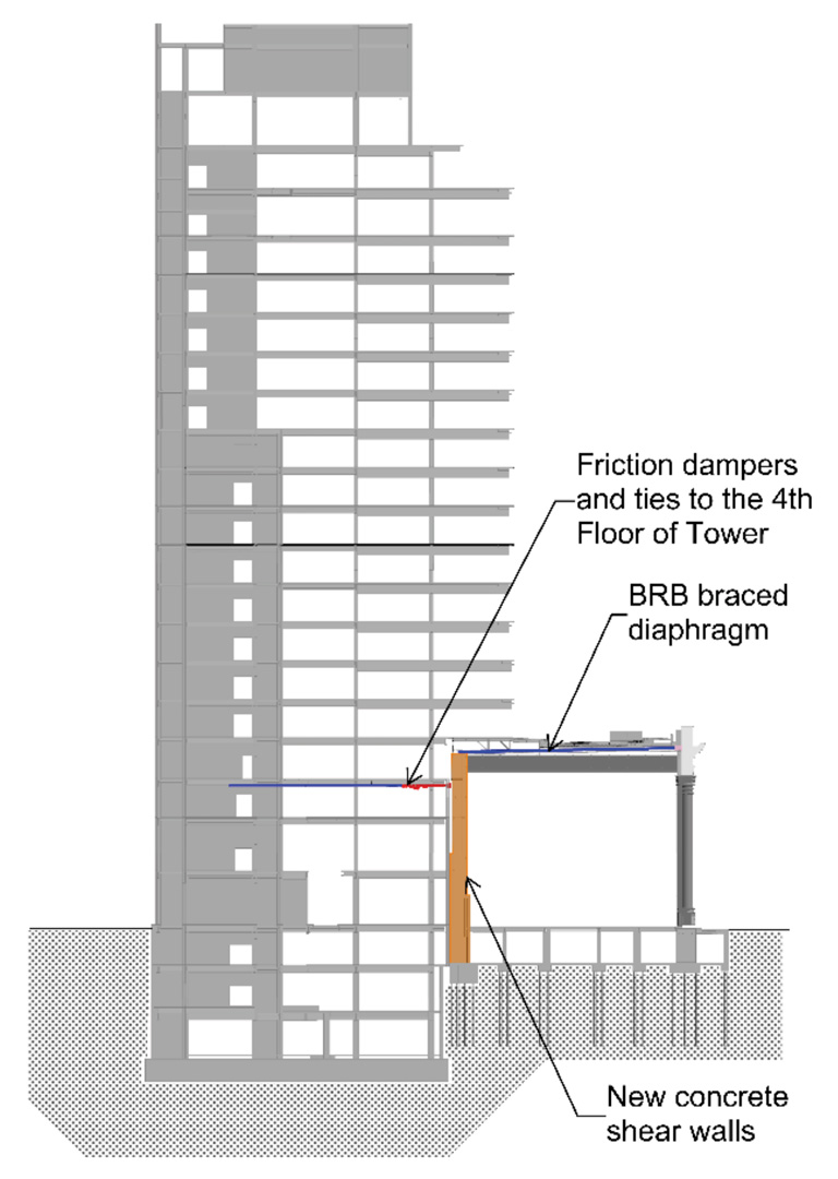
The retrofit solution focused on three main elements to address the identified seismic deficiencies: tying the Banking Hall to the Tower, the Banking Hall shear walls, and the Banking Hall roof diaphragm (Figure 3).
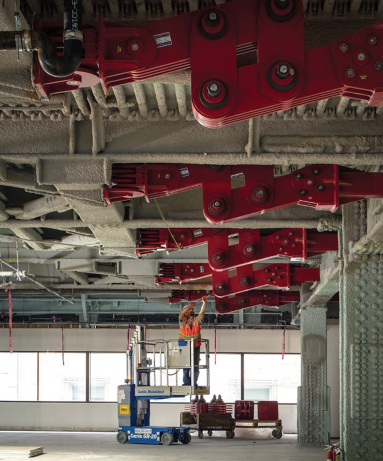
Three options were considered for tying the roof of the Banking Hall to the Tower to reduce the relative movement between buildings: solid strut connectors, viscous fluid damper connectors, and Damptech rotational friction damper connectors. The connector ties needed to limit the forces transferred to the Tower to avoid overloading it. Selected because it offered more control over the forces transferred to the Tower, its diaphragm and connections, the rotational friction damper also provided an energy dissipation mechanism that further reduced the Banking Hall seismic demands.
The rotational friction damper is comprised of steel plates sandwiching composite material friction pads clamped together by steel bolts. A total of eight rotational friction dampers with 337-kip capacity and ± 10-inch stroke tie the Banking Hall roof to the Tower. The dampers align with the Banking Hall roof steel plate girders and corresponding concrete shear walls. They hang from the Tower 4th floor framing with tube steel struts that extend across the seismic joint to connect to the Banking Hall shear walls. On the Tower side, new steel beams and struts provide a path to drag the transferred lateral loads into the main elevator and stair concrete shear wall cores.
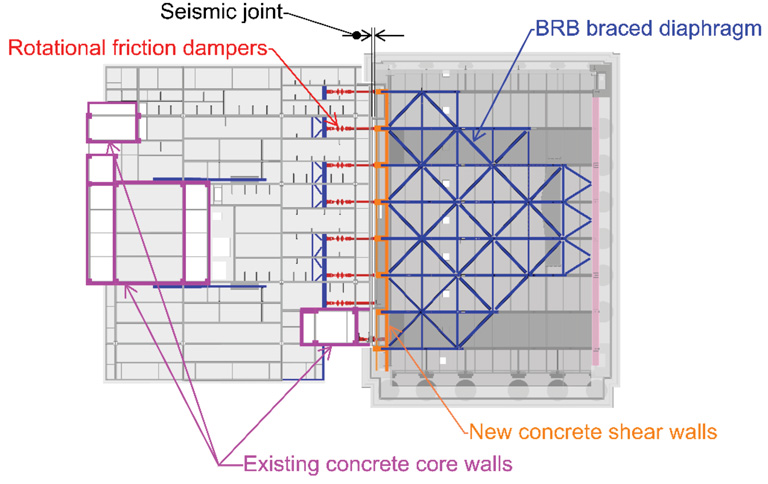
New concealed concrete walls located in the existing void/cell spaces on the Banking Hall’s west side provide the building’s primary lateral system. The new walls extend from the roof level to the basement and are highlighted in orange in Figure 4.
At the roof level, a new steel-braced diaphragm was designed to transfer the seismic forces to the new concrete shear walls on the west end of the Banking Hall (Figure 4). Buckling restrained braces were utilized and tuned to provide a ductile diaphragm while limiting deformation in the existing roof slab. The new braced diaphragm framing is located above the 1908 roof slab but concealed below the roof terrace level.
The updated NLRH analysis included the damper ties, modeled simplistically as bar elements with elastic and perfectly plastic behavior. In addition, including the strengthened Banking Hall structure in the model captured the interaction between the two structures and the damper response. The analytical models for the retrofit solution showed that approximately two-thirds of the Banking Hall roof seismic load was transferred to the Tower, and the torsional behavior was improved. Tying the two buildings together altered the global behavior of the Tower structure, with increased story forces and inter-story drifts at the floor levels near the damper connections. However, the strength and deformation capacity of the existing Tower components continued to meet the Life-Safety performance objective under the BSE-1E earthquake without requiring additional strengthening.
Even with the new dampers tying the two buildings together, an estimated ±5 inches of relative movement between the buildings is anticipated under the BSE-1E event. To avoid pounding under this earthquake and to allow the dampers to move freely as designed, the existing 3-inch seismic joint was widened to 9 1/2 inches with partial demolition of an existing low-strength concrete wall along the building joint.
Retrofit Construction
The seismic retrofit began in June 2019 with substantial completion in December 2020. While the Banking Hall and Tower maintained occupancy, construction commenced with the roof diaphragm bracing at the Banking hall and the collector ties at the 4th-floor framing of the Tower (Figures 5 & 6). Once the buildings were fully vacated, the remainder of the work commenced, including the new shear walls in the Banking Hall cells and the final tie-ins between the Banking Hall and the friction dampers in the Tower.
Since this project is the first Damptech rotational fiction damper application in the United States, the design team implemented a substantial testing and validation process. Independent testing labs performed the ASCE 41 required prototype and production tests of the damper for: seismic load testing, temperature variation testing, and loading frequency variation testing. Working closely with the damper manufacturer, a laboratory performed additional tests to validate the modeling and capacity of the dampers used for the analysis and design.
As with any existing building retrofit project, unforeseen conditions during construction created challenges. The complexity of this retrofit project added an extra level of challenges that had to be overcome. The owner, contractor, and design team worked closely to address construction access and existing condition challenges. Each required unique and innovative solutions, from processes for shotcrete application in the 11-foot by 4-foot by 65-foot tall vertical cells, to the Covid-19 outbreak and shutdown.
The seismic retrofit of the historic 400 California Street Banking Hall is both a tremendous technical achievement as well as an achievement for historic preservation. The Banking Hall has been a fixture on the corner of California and Sansome Streets for 115 years. Enduring many years of smaller earthquakes, it was uncertain if it could survive the next big seismic event. By tying the Banking Hall to the Tower and using its available strength to provide lateral resistance, the two buildings will work together to resist the next big earthquake.■
Project Team
Structural Engineer: Degenkolb Engineers, San Francisco
Owner: 400 California, LLC (a partnership between Takenaka Corporation and Kennedy Wilson International)
Architect: Gensler, San Francisco
Friction Damper Mfr: Damptech, Denmark
General Contractor: Plant Construction Company, L.P.
Steel Fabricator & Erector: Olsen Steel
Concrete Contractor: Bradley Concrete