
The seismic restoration/rehabilitation of the historic St. Mary’s in the Mountains Catholic Church, Virginia City, Nevada
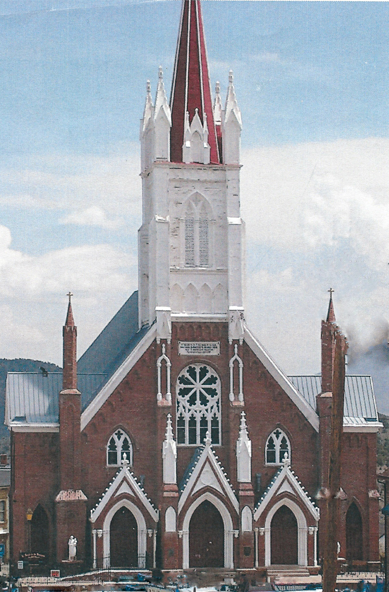
St. Mary’s in the Mountains Cathedral, built in 1876, in Virginia City, Nevada provided spiritual guidance to the rough and tumble miners of the Comstock Lode. St. Mary’s, known as the “Jewel of the Comstock”, is 170 feet to the top of the steeple and is the most prominent feature in the city. For almost a century and a half, the church has celebrated mass and is one of Virginia City’s most visited tourist attractions.
Rock and Roll is a Problem
Virginia City is located in a high seismic zone, and has the potential for large earthquakes. In a previous retrofit effort in 1970, a 3½” layer of reinforced concrete gunite was sprayed on the face of the interior walls. However, this concept did nothing to establish a competent lateral load system, nor provide proper strengthening of the wall. In the late 1990s, a structural engineering review of the church revealed it was subject to significant distress and failure from seismic activity, which threatened the life/safety occupancy of the building. The Catholic Diocese of Reno, the owners of St. Mary’s, found itself with a problem. Could the building be seismically retrofitted to provide life/safety while also preserving the architectural integrity of the historic building? St. Mary’s has a very prominent role in Virginia City’s early history, while continuing to be a visible and pronounced icon of both the city’s religious and secular history. Therefore, the Diocese decided it made sense to do a structural seismic retrofit with the caveat that the historic appearance of the building not be altered. The decision was warmly received by both the historic community and Virginia City’s general population. The Diocese then turned its attention to obtaining an engineer with the appropriate knowledge and skill in restoring historic buildings. The chosen project engineer, Paul Ferrari, P.E., has performed seismic retrofits for many of the important historic structures in Virginia City, including Piper’s Opera House, the Fourth Ward School, and the Virginia and Truckee Railroad passenger depot.
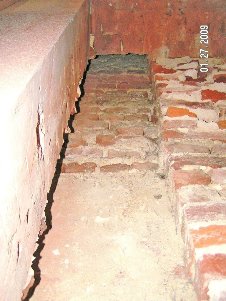
Now the hard part. One of the biggest challenges of the St. Mary’s project that Ferrari faced was how to add seismic competence to a brick building that is 146 years old without changing the historic interior and exterior look of the building. The main seismic structural concern in the building is the sanctuary’s thirty-foot high brick walls. The walls are composed of five wythes (layers) of partially fired bricks bedded in a “mortar” of mine tailings sand and slaked lime, which, without Portland cement, has no structural integrity. Wood in the Comstock to fully fire the brick kiln was expensive; as a result, the bricks are only partially fired. This creates a brick with a hard outside and a soft clay inside – think of a stale marshmallow.
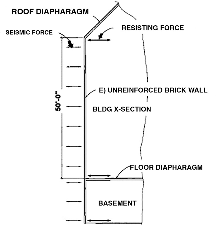
Earthquake engineering was unknown when the building was built in the 1870s. Typically, brick walls in Virginia City were constructed with a mass capable of resisting the high Zephyr winds of the Comstock. This was a lesson well learned, since the original wood church, built in 1860, was demolished in a wind storm. This resulted in brick bearing walls that have high mass with no strength, and rigidity with no ductility; not a good situation in an earthquake. Once the walls reach a certain seismic force level, they will rupture suddenly and catastrophically. The earthquake challenge is to strengthen the walls for both in-plane seismic forces and out-of-plane “pull away” seismic forces, while providing internal structural continuity between the wythes of the brick wall.
Thinking Out of the Box and Into the Walls
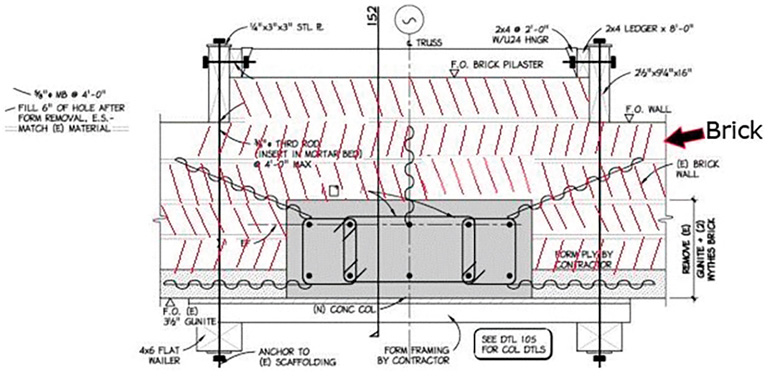
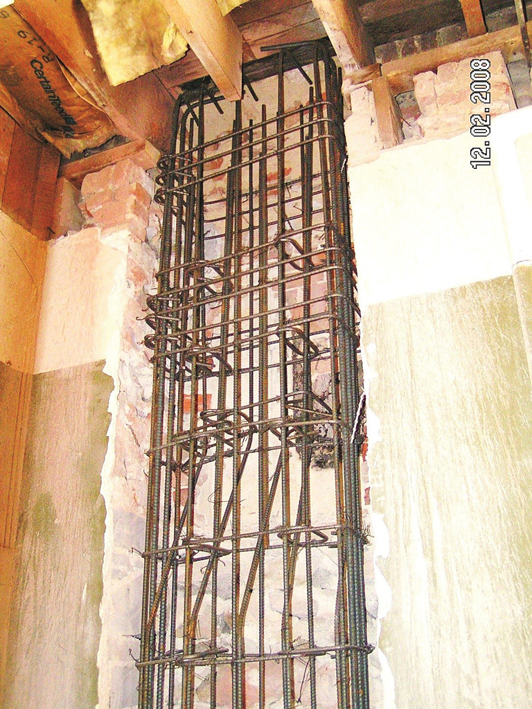
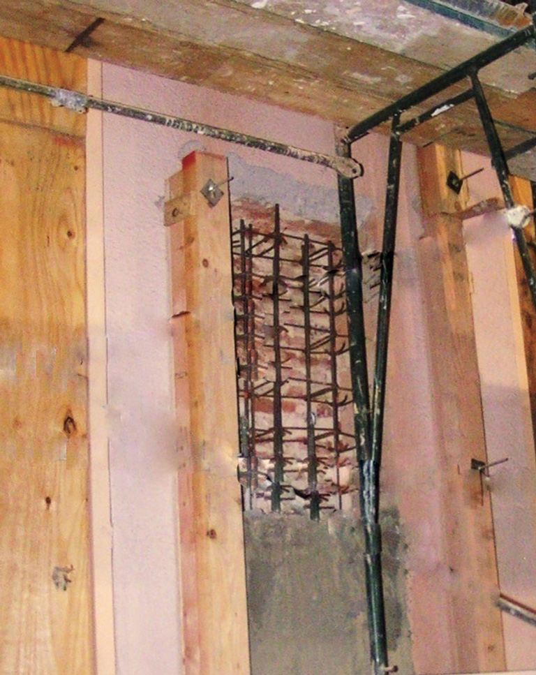
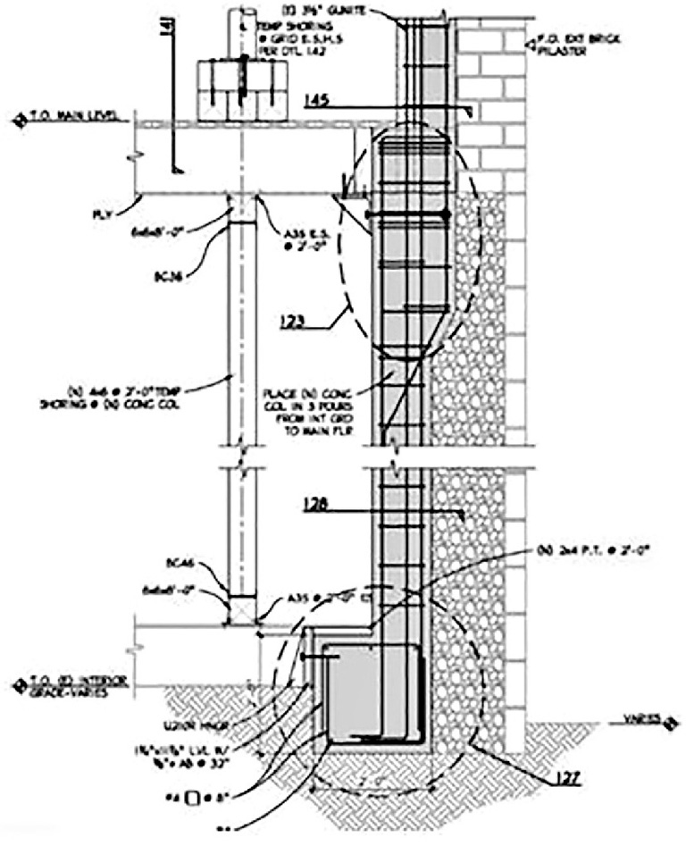
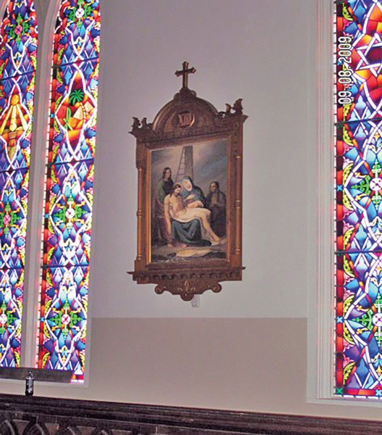
How can seismic competence be added to St. Mary’s brick walls that essentially have no strength without changing the building’s historic interior and exterior look? Engineering ingenuity was required. It was obvious that structural strength had to be integrated directly into the existing brick masonry walls. This would provide a structure capable of resisting both in-plane and out-of-plane seismic forces while also structurally strengthening the wall’s actual construction. Most importantly, the integration of structure directly into the wall would not change the historic appearance of either the interior or exterior of the building. To solve this problem, Ferrari employed a system he called “emplacement” to provide seismic strength, while retaining the essential historic character of the building. Emplacement involves integrating reinforced concrete columns and beams into the thickness of the brick bearing walls. Temporary structural shoring was installed to relieve the bearing walls of their roof and floor loading and allow the emplacement of the column strips. Since the north and south bearing walls have regular window openings along the length of the sanctuary, the most obvious location is to emplace the column strips into the three-and-a-half foot wide wall area between the windows, which extend from the roof to the basement at the north and south walls (Figure 1). The emplaced column strip is then anchored to diaphragms at the roof and floor level (Figure 2). To emplace the concrete columns, strips were saw cut into the interior face of the walls and two of the interior brick layers were removed (leaving the exterior brick layers). This creates a column strip void extending from the roof to the foundation at the inside face of the wall (Figure 3). Reinforced concrete columns, designed for in-plane shear, and out-of-plane bending are then emplaced into the void strips in the walls (Figures 4, 5). The result was a three-foot wide x twelve inches deep reinforced concrete column at a spacing of six feet on-center. The column is designed for in-plane seismic shear as a shear wall; and for out-of-plane seismic forces as a beam spanning from the floor to the roof. The net result is that the emplaced column did not alter the exterior elevation, while the interior elevation could be plastered over, identical to the original, so that no change would be visible inside the church (Figure 9).
Special care had to be taken during the concrete placement in the new column voids. Thirty feet of wet concrete hydrostatic pressure could “blow out” the exterior face brick of the wall. To avoid this, a plywood and stud panel form was constructed; one of the panels was used as the interior form of the column, the other panel was installed opposite, on the outside of the brick wall. The two forms were joined by threaded rods through the wall secured into each panel to create a “sandwich” which countered the hydrostatic concrete pressure and saved the wall (Figure 4). Also, each of the twelve column voids was only filled to one-third of the height in a round-robin sequence, so that when the next third was placed, the previous third had already set, reducing hydrostatic pressure further (Figure 6).
Whiskers
Installing the emplaced concrete columns provides the walls with overall structural seismic capability. However, the five wythes of brick in the wall needed to be better integrated between the wythes; there are few perpendicular header bricks tying the wythes together. It is possible that, during an earthquake, the exterior face brick could peel away from the wall, causing a safety problem for pedestrians below, and ruining the historic appearance of the church. To help prevent this, Simpson stainless steel quarter-inch diameter helical anchors “whiskers” were helically screwed into the brick layers from the new columns voids every thirty inches vertically. The five anchors at each level were installed in a “splayed” configuration. The anchors were screwed through the brick layers and penetrated into the exterior wall’s back face brick (Figure 4). The butt end of the steel whiskers is captured by the structural concrete in the new column, anchoring the whiskers, and therefore, the brick in place to prevent brick spalling. The splayed arrangement of the whiskers from adjacent columns strips also helped to secure the brick areas above and below the windows, stabilizing the face brick in the unreinforced wall areas.
Lateral Load Structural Concept
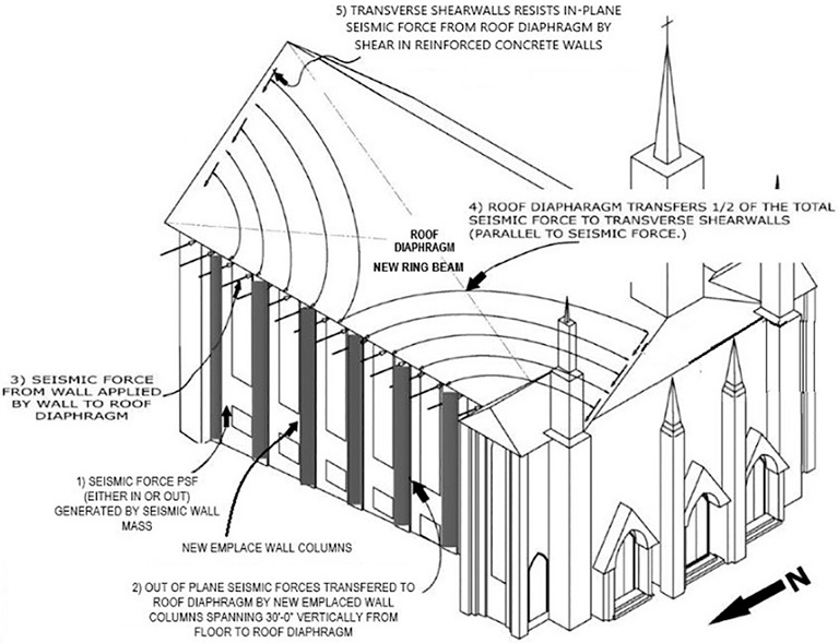
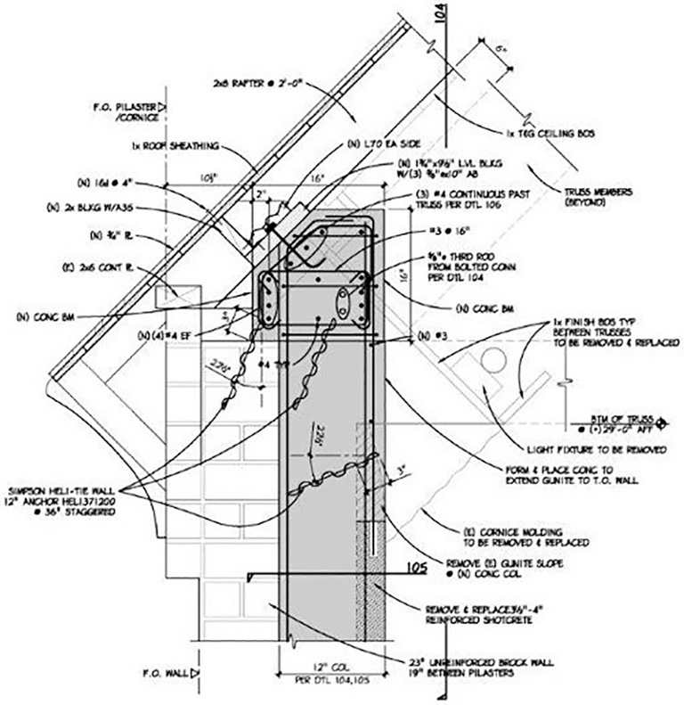
Although the new concrete column emplacement in the walls provides a structural system to resist seismic loadings on the walls, it is only part of the needed total seismic lateral load system. The in-plane and out-of-plane seismic loads in the emplaced columns had to be integrated into a coherent lateral load concept for the overall building. To accomplish this, the top of the new emplaced column were anchored into a new horizontal sixteen-inch high x twelve-inch wide concrete “ring beam”. The ring beam extends around the entire building along the top of the existing walls in the void between the top of the wall and the bottom of the roof. The ring beam, in turn, transfers both out-of-plane and in-plane seismic forces from the emplaced columns to a new plywood roof diaphragm that was glued and nailed into the existing plank roof (Figure 7). The diaphragm force is then transferred to the parallel east and west walls that have been reinforced and tied into the ring beam and roof diaphragm. The concrete ring beam is hidden from interior view by the original ornate wood crown molding that was salvaged and reused. The emplaced columns are also tied to a new horizontal plywood diaphragm at the bottom of the sanctuary floor joists. Placing the new plywood diaphragm at the bottom of the floor joists (ceiling of the basement) preserves the historic floor above, while transferring out-of-plane seismic forces to ground via new basement shearwalls (Figures 2, 8).
Conclusions
The emplacement concept was a success for St. Mary’s. It met all of the original structural design constraints: a competent structural seismic system was integrated into the building, and the historic interior and exterior appearance was unchanged (Figure 9). In 2009, the cost of the structural portion of the retrofit was $1,500,000.
The emplacement concept is driven by a specific set of constraints that may be unique to St. Mary’s in the Mountains. The Church is located in a high seismic zone. The owner required that the historic appearance of the building be maintained. And most importantly, the bearing walls were constructed with “mortar” that had no Portland cement and no structural value; essentially, the walls have no modulus of elasticity. This last consideration was the most difficult and generated the need for the emplacement concept. This is probably not a widespread condition in most historic buildings. St. Mary’s wall construction is essentially a product of Virginia City’s mining boom where the builders made do with locally available materials. Unless similar conditions exist in a historic structure retrofit, particularly in the wall strength, it is unlikely that the emplacement method would be appropriate. However, if these conditions are present, emplacement may be the only concept that addresses all of the building’s constraints.■
Project Team
Engineer of Record: Paul A. Ferrari, P.E.
Owner’s Representative: Mike Quilici
Project Manager: Robert Wright
Contractor: Reyman Brothers Construction