
It has never been easier
The design and assessment of concrete elements are typically performed at the sectional (1-D element) or point (2-D element) level. This procedure is described in all structural design standards, e.g., the American Concrete Institute’s ACI 318-19, Building Code Requirements for Structural Concrete and Commentary, EN 1992-1-1, Eurocode 2: Design of Concrete Structures, or the International Federation for Structural Concrete (fib) Model Code. All of these standards are used in everyday structural engineering practice. However, it is not always understood that the procedure is only acceptable in areas where the Bernoulli-Navieri hypothesis of plane strain distribution applies (referred to as B-regions). The places where this hypothesis does not apply are called discontinuity or disturbed regions (D-Regions). Examples of B and D regions of 1-D elements are shown in Figure 1.
These include bearing areas, parts where concentrated loads are applied, locations where an abrupt change in the cross-section occurs, openings, etc. In addition, designers meet a lot of other D-Regions, such as walls, bridge diaphragms, corbels, etc., when designing concrete structures.
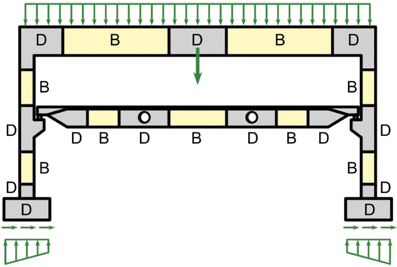
Figure 1. Discontinuity regions (D).
In the past, semi-empirical design rules were used for dimensioning discontinuity regions. Fortunately, these rules have been largely superseded over the past decades by Strut-and-Tie (S&T) models and stress fields, featured in current design codes and frequently used by designers today. These models are mechanically consistent and powerful tools. Note that stress fields can generally be continuous or discontinuous and that strut-and-tie models are a special case of discontinuous stress fields.
Despite the evolution of computational tools over the past decades, Strut-and-Tie models are primarily used as hand calculations. Consequently, their application for real-world structures is tedious and time-consuming since iterations are required, and several load cases need to be considered. Furthermore, this method is unsuitable for verifying serviceability criteria (deformations, crack widths, etc.).
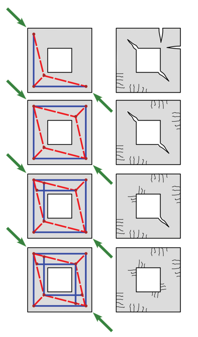
Why use a nonlinear solution for discontinuity regions? First, a general solution for walls with openings does not exist in the design codes. The creation of the S&T model must respect the fact, among others, that the tensile strength of the concrete is negligible. Therefore, if concrete is attributed with the ability to transfer just the compressive forces and steel with the ability to transfer only the tensile forces, the result is a very simple truss model consisting of elements exclusively under tension or compression. The strut and tie model must express the behavior of the structure in the limit state. The creation of the model thus cannot be accidental, but it must correspond to the conditions of the lower bound and upper bound theorems. The impact of rebar positions on the mode of failure and crack propagation is demonstrated in the example in Figure 2.
Engineers often use the linear-elastic 2-D model to determine stress flow into the wall to better predict the S&T geometry. Sometimes the results obtained from the linear-elastic analysis are directly used for the code check. However, structural behavior obtained from nonlinear analysis might differ from linear-elastic analysis (Figure 3).
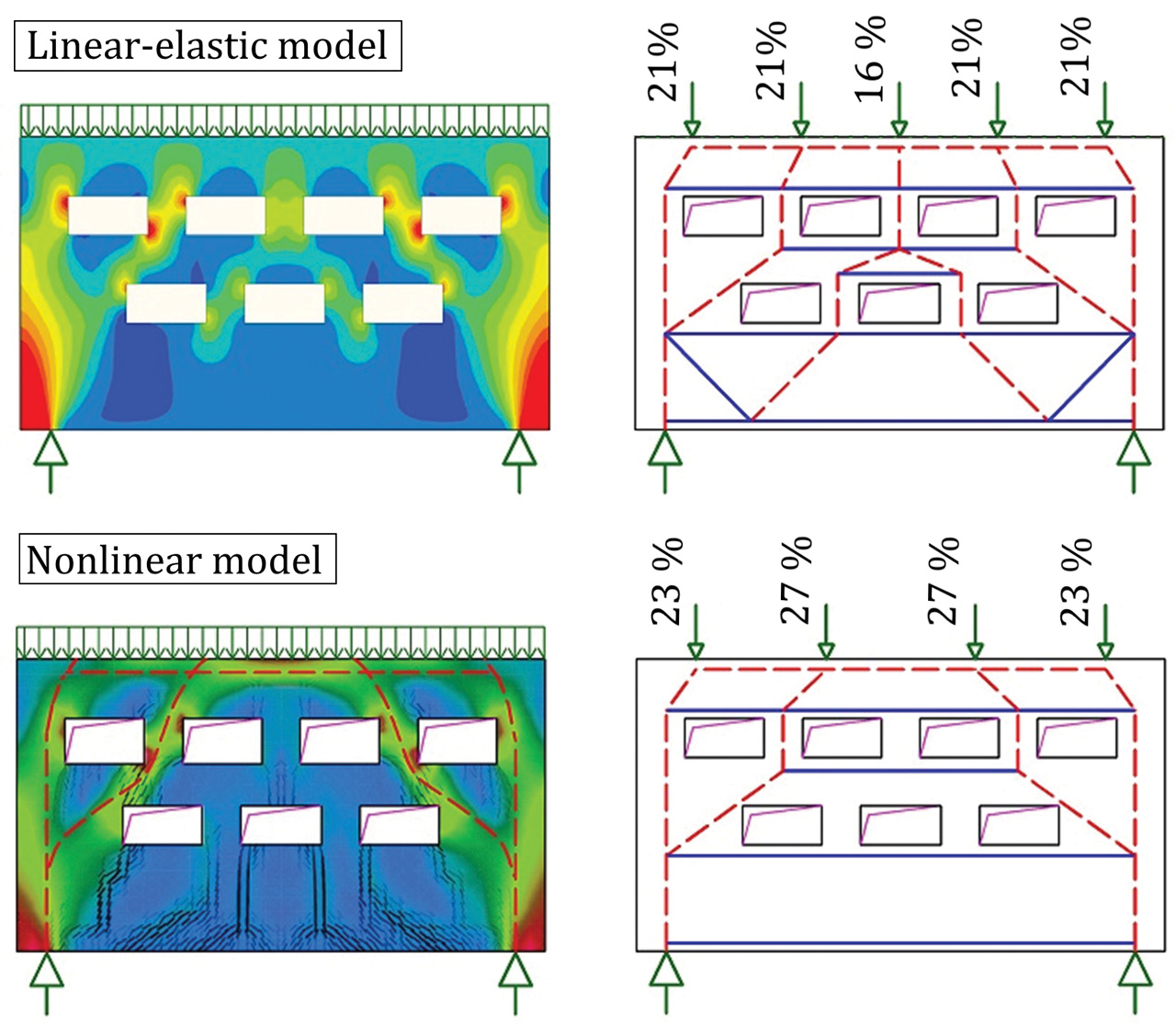
The cracks in the reinforced structure cause stiffness changes, leading to stress redistribution in a structural volume. Linear analysis often overestimates stresses in concrete. Stress peaks calculated by linear elastic analysis are smoothed thanks to nonlinear plastic material models defined by design codes, which correspond to real structural behavior
The Compatible Stress Field Method
The interest of structural engineers in a reliable and fast tool to design D-regions led to the development of the new Compatible Stress Field Method (implemented in IDEA StatiCa Detail), a computer-aided stress field design method that allows the automatic design and assessment of structural concrete members subjected to in-plane loading.
The Compatible Stress Field Method (CSFM) is a 2-D continuous finite element (FE)-based stress field analysis method in which classic stress field solutions are complemented with kinematic considerations, i.e., the state of strain is evaluated throughout the structure. Hence, the effective compressive strength of concrete can be automatically computed based on the state of transverse strain in a similar manner as in compression field analyses that account for compression softening and the elastic-plastic stress field (EPSF) method. Moreover, the CSFM considers tension stiffening, providing realistic stiffnesses to the elements, and covers all design code prescriptions (including serviceability and deformation capacity aspects) not consistently addressed by previous approaches. The CSFM uses common uniaxial constitutive laws provided by design standards for concrete and reinforcement. These are known at the design stage, allowing load and strength reduction factors to be used. Hence, designers do not have to provide additional, often arbitrary material properties as are typically required for nonlinear finite element analyses, making the method perfectly suitable for engineering practice.
The finite element model is composed of several types of finite elements (Figure 4):
- 1-D reinforcement element,
- 2-D concrete element,
- Special 2-D bond element,
- Rigid body and interpolation constraints (Multi-Point Constraints, MPC) between elements.
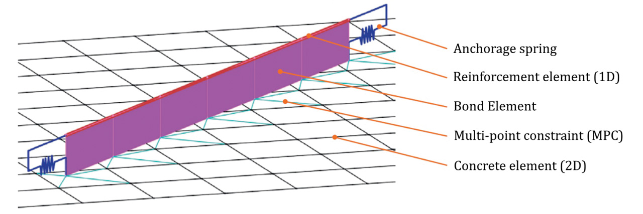
The last two are used for bond modeling. Furthermore, the latter enables the concrete and reinforcement finite element mesh to be created independently. The first type consists of two-node rod elements for which only axial stiffness is considered. The second type consists of four-node and three-node isoparametric flat plate elements considering a plane state of stresses. The Newton-Raphson algorithm is used to solve the set of nonlinear equations.
The CSFM assumes fictitious, rotating, stress-free cracks that open without slip (Figure 5a) and considers the equilibrium at the cracks together with the average strains of the reinforcement. Hence, the model considers maximum concrete (σc3r) (Figure 5b) and reinforcement stresses (σsr) (Figure 5d) at the cracks while neglecting the concrete tensile strength (σc1r = 0), except for its stiffening effect on the reinforcement. The consideration of tension stiffening allows the average reinforcement strains (εm) to be simulated (Figure 5c).
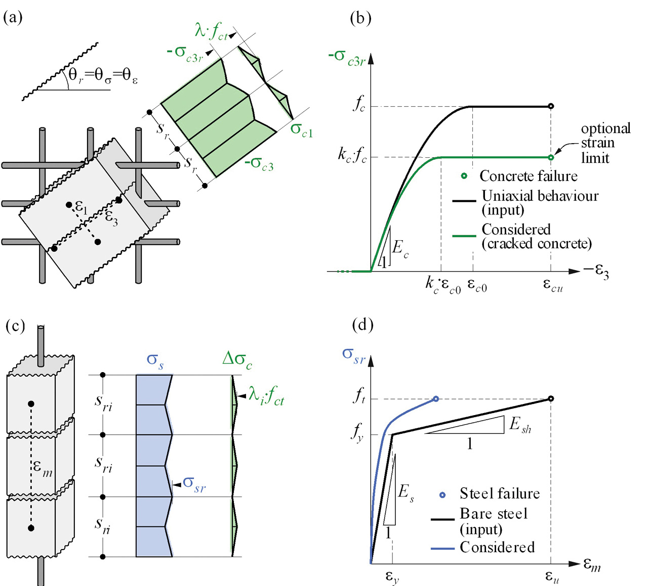
Despite their simplicity, similar assumptions have been demonstrated to yield accurate predictions for reinforced members subjected to in-plane loading if the provided reinforcement avoids brittle failures at cracking. Furthermore, the non-consideration of any contribution of the tensile strength of concrete to the ultimate load is consistent with the principles of modern design codes, which are mainly based on plasticity theory.
However, the CSFM is not suited for slender elements without transverse reinforcement since relevant mechanisms for such elements as aggregate interlock, residual tensile stresses at the crack tip, and dowel action – all of them relying directly or indirectly on the tensile strength of the concrete – are disregarded. While some design standards allow the design of such elements based on semi-empirical provisions, the CSFM is not intended for this potentially brittle structure.
An advantage of nonlinear analysis is the ability to calculate serviceability limit states such as crack width and deflection. The reduction of crack width protects reinforcement against corrosion and extends the structure’s lifetime. The serviceability analysis contains certain simplifications of the constitutive models used for ultimate limit state analysis. The plastic branch of the stress-strain curve of concrete in compression is disregarded, while the elastic branch is linear and infinite. Compression softening law is not considered. These simplifications enhance the numerical stability and calculation speed and do not reduce the generality of the solution as long as the resultant material stress limits at serviceability are clearly below their yielding points (as required by design codes). Therefore, the simplified models used for serviceability are only valid if all verification requirements are fulfilled.
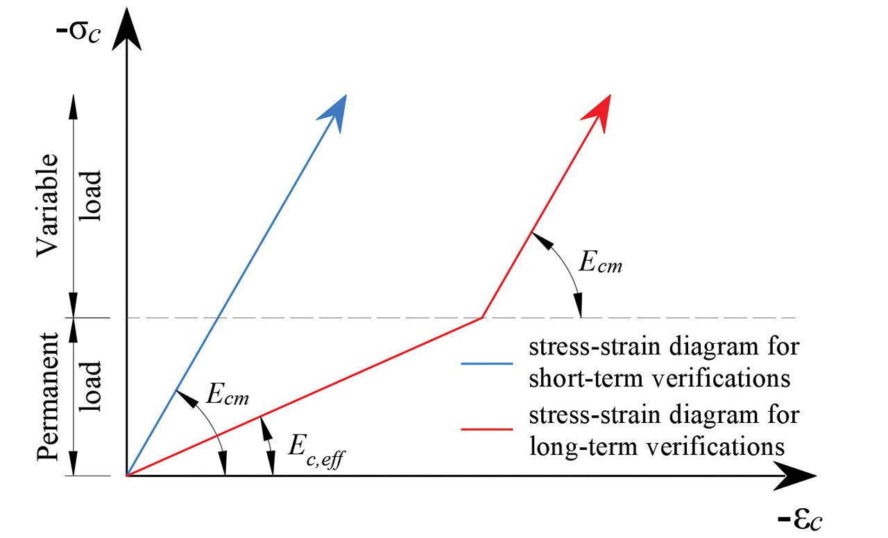
Due to concrete creep, the long-term effects of the deflection must be considered. Reducing the modulus of elasticity of the concrete reduces the stiffness of the structure, which leads to a redistribution of stresses in the element and an increase in deformation (Figure 6).
Practical Examples
Walls with Openings
Concrete walls and deep beams are common load-bearing elements in building structures. However, these bearing structures are very often weakened by openings for piping, doors, window, and more.
When designing complex structures, engineers commonly create global models in 3-D analysis programs, from which the internal forces are used to design the individual structural elements. As an example, consider a wall with a door opening. The wall is 9.75 feet (3.0m) high, 18.5 feet (5.7m) wide, 12 inches (0.3m) thick, and is located in the basement of a multistory residential building and founded on piles. The loads on each edge of the wall are taken from a global model created by Scia Engineer (Figure 7).
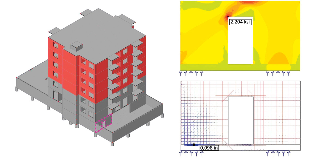
CSFM includes tools such as Linear Analysis or Topology Optimization based on finite element calculations. Based on the geometry of the structure and the selected loads, the areas of the wall most subjected to compression and tension are determined, serving as a guide for the design of the reinforcement.
When defining the reinforcement, reinforcing bars need to be added around the door opening. Significant tensile stresses are often generated at the corners of the opening, so it is appropriate to insert inclined reinforcing bars to prevent wide cracks.
The calculation results in the stress assessment in both concrete and reinforcement for the ultimate limit state. The most significant stress in the concrete occurs at the top of the wall. Due to the pile bearing, wall deformation causes bending in the vertical direction. In addition, the inclined concrete compression strut in the left part of the wall causes large transverse tensile strains resulting in wide cracks and, at the same time, a reduction in the compressive strength of the concrete in this area.
Corbels (Brackets)
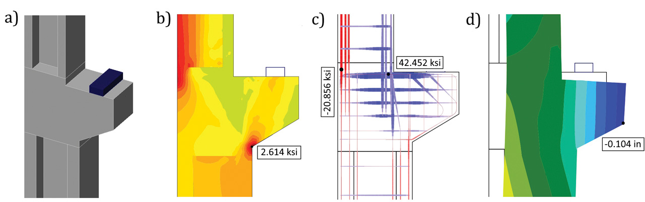
In industrial buildings, a common structural element is a corbel (bracket) that transmits high intensities of shear force and bending moment from the horizontal structure (beam) to the column. Such stresses cause a complex load transfer in the relatively small volume of the reinforced concrete element, resulting in a nonlinear behavior of the individual stress components. The geometry of S&T models defined in design standards such as ACI 318-19 or EN 1992-1-1 can be used to design a new structure. The disadvantage is that only the ultimate load capacity of the cantilever can be determined using these models without knowledge of the deformation behavior of the structure. Furthermore, the absence of a crack width check can lead to unsafe design if the corbel is placed in the aggressive environment of a production hall and corrosion of the reinforcement occurs after the formation of wide cracks.
Many engineering structures used for production purposes (factories, warehouses) were built decades ago. Due to the influence of time, material degradation, and increased demands on the structure due to increased production, individual parts of the structures do not meet the requirements for their safe use. For example, engineers designed corbels in the last century according to beam theory, leading to inappropriate shear reinforcement layout design. Today, methods of strengthening corbels based on post-tensioning are known. However, existing S&T models cannot adequately capture the effect of prestressing on the structure. Using the nonlinear CFSM method can capture not only the actual deformation behavior of the structure at ultimate and serviceability limit states but also check the width of the cracks developed and thus ensure the structure’s durability (Figure 8).
Conclusion
Structural analysis and design of concrete structures is a challenging task – both because of the natural complexity of the subject and because of the regulation an engineer has to comply with to get the project done. Limit analysis methods, in general, and Strut-and-Tie models and stress fields, in particular, are powerful tools for designing concrete structures. They are transparent, allow one to trace the flow of forces, and give the engineer control over the design. However, they are typically used as hand calculations, making their application tedious and time-consuming since iterations are required and several load cases need to be considered. In addition, they are not directly applicable for checking serviceability criteria, and the influence of prestressing is challenging to capture.
The construction process has never been as fast as it is today, and the pressure on the cost-effectiveness of structures is growing with zero tolerance for structural defects. In such an environment, engineers are pushed to work quicker, more accurately, and reliably than ever. And they need a different set of tools for that. The development trend of computing software should provide engineers with a generic, complete, and easy-to-use solution for designing and code-checking structural elements, cross-sections, and details following applicable standards. Complete code-checks for ultimate and serviceability limit states (including crack widths calculation) allow engineers to sleep peacefully
Acknowledgment
This paper and its research would not have been possible without the cooperation of the Swiss Federal Institute of Technology (ETH) Zurich. Professor Walter Kaufmann, the Chair of Structural Engineering (Concrete Structures and Bridge Design), and his research team focus on the load-deformation behavior of structural concrete, the structural safety evaluation of existing bridges and buildings, innovative structures and bridges, as well as interdisciplinary research projects. They have done exceptional work validating and verifying the CSFM method and securing code-compliancy with design codes.■
References
Kraus, M., M. Weber, W. Kaufmann, and L. Bobek 2022. Numerical analysis of experimentally tested frame corners with opening moments using the Compatible Stress Field Method (CSFM). In Computational Modelling of Concrete and Concrete Structures, pp. 694-03. CRC Press. https://doi.org/10.1201/9781003316404
Bobek, L., Juříček, L., Číhal, M., and Kabeláč, J., Konečný, M., 2020. Verification and Validation of Corbels Strengthened by Unbonded Tendons and Bars. SSP 309, 157-162.
https://doi.org/10.4028/www.scientific.net/ssp.309.157
Kaufmann, W. 1998. Strength and Deformations of Structural Concrete Subjected to In-Plane Shear and Normal Forces. Basel: Birkhäuser Basel. https://doi.org/10.1007/978-3-0348-7612-4
Kaufmann, W., and P. Marti. 1998. “Structural Concrete: Cracked Membrane Model.” Journal of Structural Engineering 124 (12): 1467-75. https://doi.org/10.1061/(ASCE)0733-9445(1998)124:12(1467)
Mata-Falcón, J., D.T. Tran, W. Kaufmann & J. Navrátil 2018. Computer-aided stress field analysis of discontinuity concrete regions. In Computational Modelling of Concrete and Concrete Structures, pp. 641–650. CRC Press.
https://doi.org/10.1201/9781315182964