
Flexural analysis and design of beam sections are fundamental topics in reinforced concrete structures. However, many engineers and students have difficulty generalizing the basic analysis and design principles into more general and complex cross-sectional shapes other than simple rectangular cross-sections. This article presents the flexural analysis and design of general beam sections in a rigorously derived framework and builds a foundation for their design. Part 1: Section Analysis focuses on the flexural strength calculation (analysis) of any given beam section. Part 2: Section Design focusing on the flexural design aspects of beam sections will run in a future article.
For symbols not defined in this article, please refer to the American Concrete Institute’s ACI 318-19, Building Code Requirements for Structural Concrete.
Section Analysis Basics
Assumptions
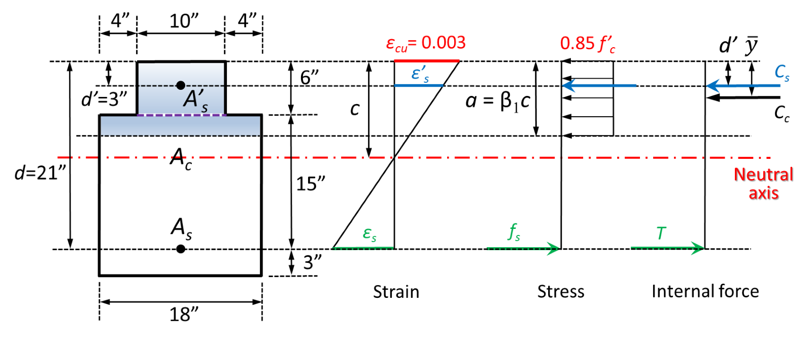
Figure 1 shows a reinforced concrete beam section’s strain, stress, and internal force diagrams. Several assumptions are made to compute the nominal flexural strength of the section. The plane sections normal to the beam axis remain plane so that the strain diagram is linear. According to ACI 318-19: 22.2.2.1, the maximum strain at the extreme concrete compression fiber is assumed to be 𝜀cu=0.003.
The concrete stress of 0.85f‘c(f‘c is the specified compressive strength of concrete) is assumed uniformly distributed over an equivalent compression zone, Ac (ACI 318-19: 22.2.2.4.1); this is referred to as the Whitney stress block.
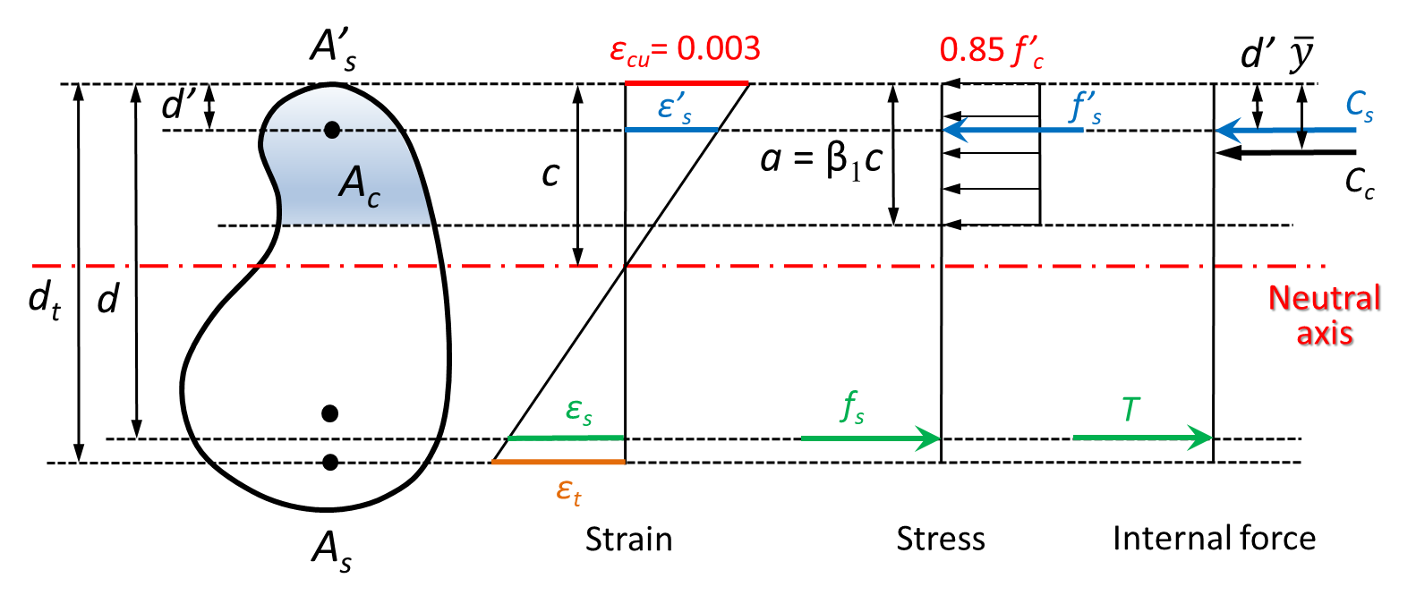
To compute the nominal flexural strength of a beam section, equilibrium of tension and compression is maintained, i.e.,

The resultant tension and compression forces are


where As and A’s are the tension and compression steel areas, and their respective stresses are fs and f’s . The strains in the tension and compression steel are 𝜀s and 𝜀‘s respectively. For singly reinforced sections, A’s=0 and Cs=0. For doubly reinforced sections, it is common to use an approximate equation of Cc, as

The equilibrium equation is written as

The design moment strength of a singly reinforced beam section is

and the design moment strength of a doubly reinforced beam section is

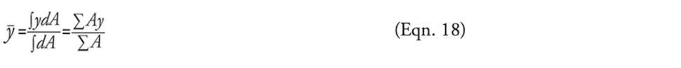
where y is the distance from the center of gravity or centroid of Ac to the extreme concrete compression fiber. This represents the location of the resultant concrete compression, Cc. In Equations 7 and 8, d and d’ are the distances from the centroids of the tension and compression steel groups to the extreme concrete compression fiber, respectively.
ACI 318-19
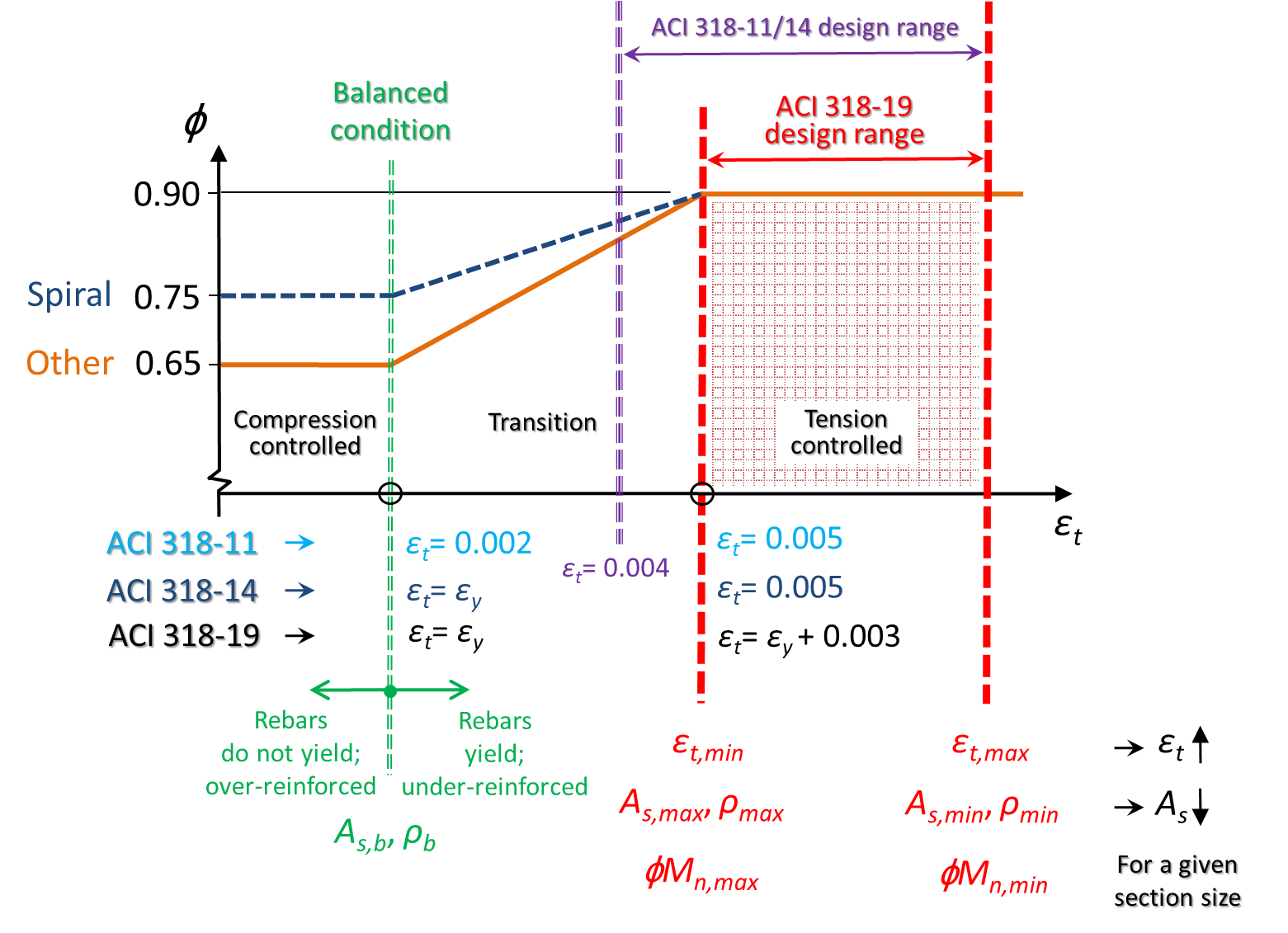
To determine the strength reduction factor, 𝜙, ACI 318-19 Table 21.2.2 defines the following three types of beam sections, depending on the ductility of the sections:
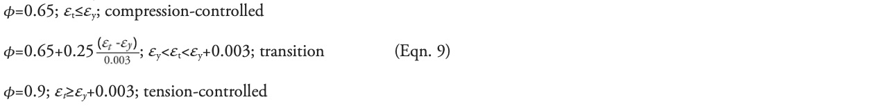
where 𝜀t is the strain in the extreme (bottom) layer of tension steel and is calculated based on dt, which is the distance from the centroid of the extreme layer of tension steel to the extreme concrete compression fiber. The yield strain of steel is

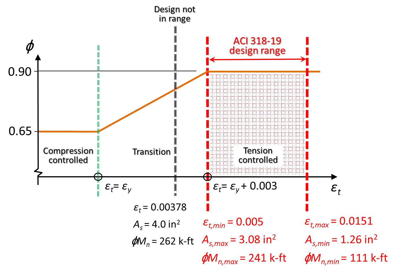
ACI 318-19 defines 𝜀t=𝜀y+0.003 as the start of tension-controlled sections instead of 𝜀t=0.005, which was used in previous ACI 318 editions. For Grade 60 steel, ACI 318-19 is consistent with the two previous editions. The difference between ACI 318-11, ACI 318-14, and ACI 318-19 is shown in Figure 2. Before ACI 318-19, a transition section with 0.005>𝜀t≥0.004 is allowed for beam design; however, in ACI 318-19, only tension-controlled sections (𝜙=0.9) are permitted, i.e., 𝜀t ≥ 𝜀y+0.003.
Rectangular Sections
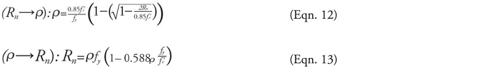
For rectangular beam sections, the relationship between the reinforcement ratio, 𝜌=As /bd and strain, 𝜀t , is as follows:

The design moment strength of a rectangular section is

where Rn is the flexural-resistance factor and is a quadratic function of 𝜌. Depending on the given information, the rectangular section analysis and design may involve two types of calculations, i.e., Rn⟶ 𝜌 or 𝜌⟶Rn, as
Section Analysis Procedure
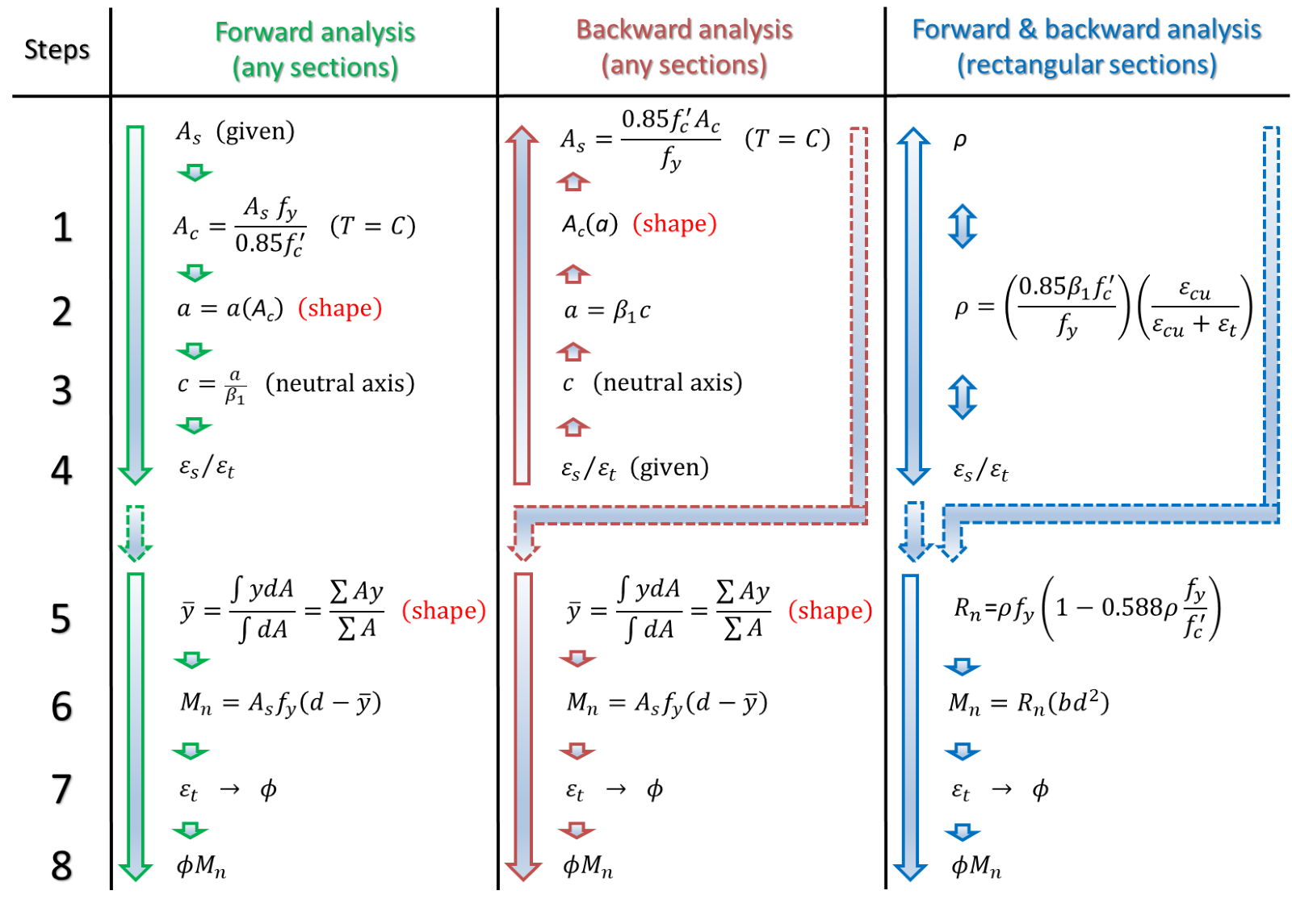
For singly or doubly reinforced concrete beam sections, the analysis procedure includes 8 or 12 steps:
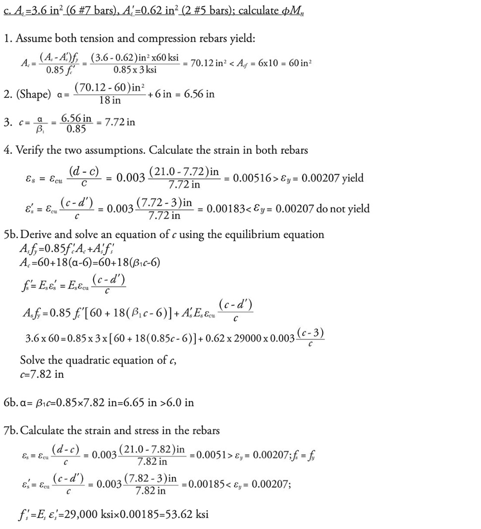
1. Assume all rebars yield. Based on the equilibrium condition, for a singly reinforced section

For a doubly reinforced section

2. (Shape) Calculate the depth of the Whitney stress block, α=α(Ac), and α is a function of Ac which depends on the shape of the cross-section.
3. Calculate the neutral axis depth, c= α/𝛽1.
4. Verify the assumption that all rebars yield.
For a singly reinforced section, calculate the strain in the rebars

and checking whether this is greater than or equal to the yield strain of steel, 𝜀y.
If the rebars yield, i.e., 𝜀s ≥ 𝜀y⟶ fs =fy , continue to steps 5a-8a; otherwise, go to steps 5b-12b.
For a doubly reinforced section, calculate the strains in both tension and compression rebars
and checking whether 𝜀s and 𝜀‘s are greater than or equal to the yield strain of steel, 𝜀y .
If both tension and compression rebars yield, i.e., 𝜀s ≥𝜀y ⟶
fs =fy , and 𝜀‘s ≥𝜀y ⟶f’s= fy , continue to steps 5a-8a; otherwise (if only tension rebars yield, or if only compression rebars yield, or if neither rebars yield), go to steps 5b-12b.
5a.(Shape) Calculate the center of gravity or centroid of Ac, which depends on the shape of the cross-section.
5b. Derive and solve an equation of c using the equilibrium equation. For a singly reinforced section
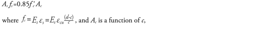
depending on the shape.
For a doubly reinforced section

and Ac is a function of c, depending on the shape.
6a. Calculate the flexural strength Mn using Equation 7 or Equation 8.
6b. Calculate α=𝛽1/c.
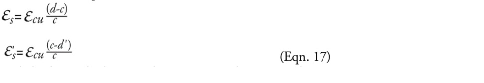
7a. Calculate the strain in the extreme (bottom) layer of tension steel using

and determine the type of section (i.e., compression-controlled, transition, or tension-controlled section) and 𝜙.
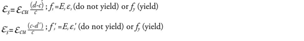
7b. Calculate the strain and stress in the rebars. For a singly reinforced section

For a doubly reinforced section
8a. Compute 𝜙Mn.
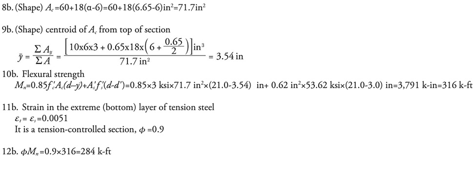
8b. (Shape) Calculate the area of the equivalent compression zone, Ac = Ac(α), and Ac is a function of α. This step depends on the shape of the cross-section.
9b. (Shape) Calculate centroid of Ac,

10b. Calculate the flexural strength Mn using Equation 7 or Equation 8.
11b. Calculate the strain in the extreme (bottom) layer of tension steel using

12b. Compute 𝜙Mn.
Forward and Backward Analysis
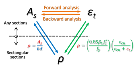
This section introduces the forward and backward analysis of singly reinforced beam sections, which are shown in Figure 3.
The forward analysis starts with the given section and steel area, As , as

In the backward analysis, the strain value of the tension steel is given, and the steel area can be determined as

The nominal moment strength can be computed for both the forward and backward analysis, as shown in Figure 3. Since these are mainly used for design purposes, the tension steel is assumed to yield. The relationship between As , 𝜀t , and 𝜌 is shown in Figure 4.
Lower and Upper Bounds
For any beam cross-section, the minimum and maximum areas of reinforcement allowed in a singly reinforced section can be calculated. For a given section size, the corresponding design moment strength values are the minimum and maximum values that can be determined, as shown in Figure 2. These lower and upper bounds define the permitted range of a beam section design based on ACI 318-19.
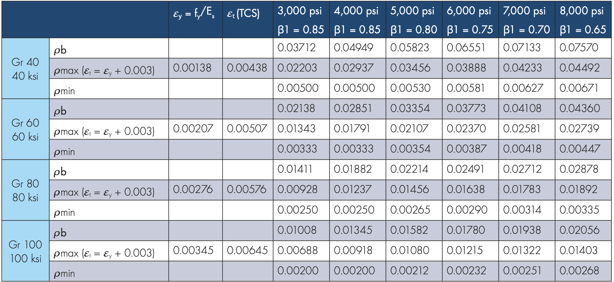
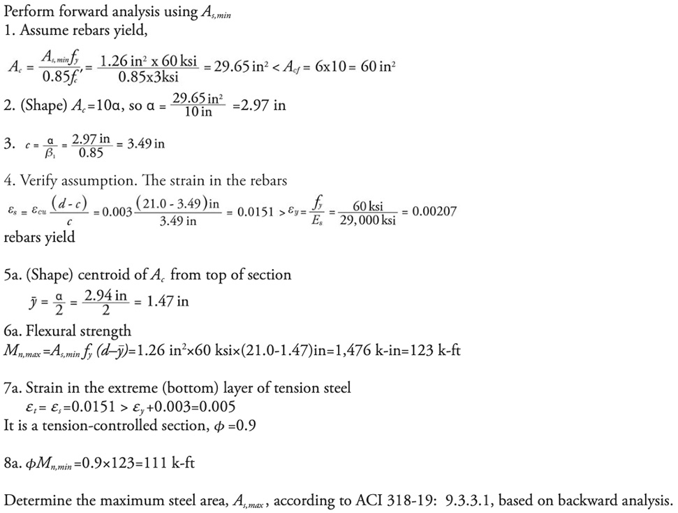
The minimum steel area is determined according to ACI 318-19: 9.6.1.2. ACI 318-19: 9.3.3.1 indirectly specifies the maximum steel area requirement. A beam section has to be designed as tension controlled (𝜙=0.9), and the strain 𝜀t shall be greater than or equal to (𝜀y+0.003), which is a lower bound strain value. A backward analysis is required to determine the maximum steel area permitted in a singly reinforced beam section. In many cases, the maximum steel area requirement controls the beam design to reduce the beam size and weight that may be required for architectural considerations or other reasons.
For the analysis and design of rectangular sections, it is straightforward to check the lower and upper reinforcement ratio limits directly. The balanced reinforced ratio 𝜌b and maximum reinforcement ratio 𝜌max can be directly determined using Equation 10, and these values, as well as the minimum reinforcement ratio, 𝜌min, are listed in the Table. The minimum and maximum design moment strength of a rectangular section can be computed using Equation 13, (𝜌⟶Rn), and Equation 11.
A Numerical Example
Given a beam section, as shown in Figure 5, use f’c =3,000 pounds per square inch (psi) and Grade 60 rebars (fy =60 kips per square inch [ksi]). The beam section is analyzed using the forward and backward analysis methods outlined in this article. Consider the following cases:
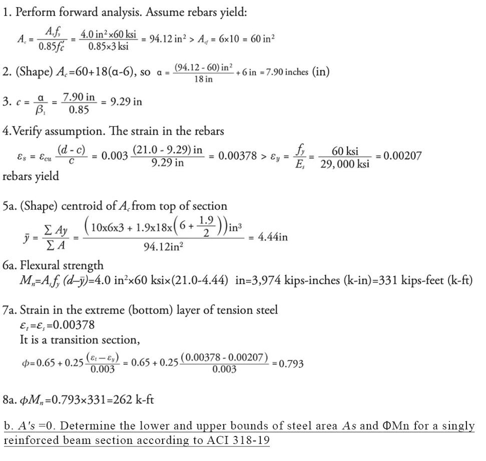
a. As = 4.0 square inches (in2) (4 #9 bars), A’s=0; calculate 𝜙Mn ;
b. A’s= 0. Determine the lower and upper bounds of steel area As and 𝜙Mn for a singly reinforced beam section according to ACI 318-19;
c. As = 3.6 in2 (6 #7 bars), A’s=0.62 in2 (2 #5 bars); calculate 𝜙Mn.
a. As = 4.0 in2 (4 #9 bars), A’s=0; calculate 𝜙Mn
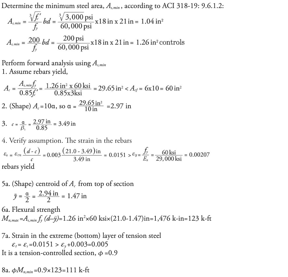
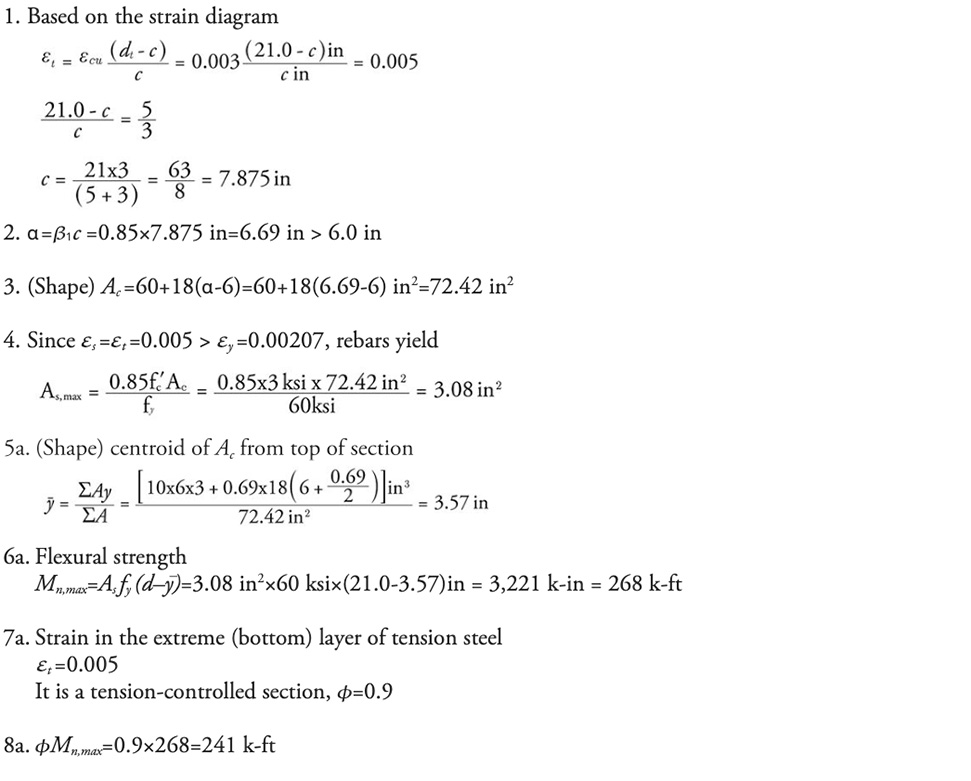
So the range of steel area permitted by ACI 318-19 is 1.26 in2 – 3.08 in2, and the corresponding moment strength range is 111 k-ft – 241 k-ft. However, the design (4 #9 bars) in Part a is not in this range since it is not a tension-controlled section, as seen in Figure 6.
Summary
- Different analysis methods for reinforced concrete beam sections are available, such as the trial-and-error approach. This article presents a general analysis framework of singly reinforced and doubly reinforced general beam sections. This is a rigorously derived approach for any general section, which can be done by hand or implemented in a spreadsheet.
- The latest ACI 318-19 code requirement for flexural strength is introduced, and the difference between this edition and previous editions of ACI 318 is briefly reviewed.
- The steel area range and flexural strength range permitted by ACI 318-19 for singly reinforced beam sections are discussed and can be computed for any cross-sectional shape. This provides the lower and upper bounds for a new beam design.
- This article serves as supplementary material to any reinforced concrete textbook for a better understanding of the topic.
- Part 2 of this article, in a future issue, will discuss the flexural design of beam sections.
REFERENCES
- ACI (American Concrete Institute). 2011. Building Code Requirements for Structural Concrete and Commentary. ACI 318-11, Farmington Hills, Michigan.
- ACI (American Concrete Institute). 2014. Building Code Requirements for Structural Concrete and Commentary. ACI 318-14, Farmington Hills, Michigan.
- ACI (American Concrete Institute). 2019. Building Code Requirements for Structural Concrete and Commentary. ACI 318-19, Farmington Hills, Michigan.
- McCormac, J. C., Brown, R. H. 2015. Design of Reinforced Concrete, 10th Edition. Wiley, Hoboken, New Jersey.