
19th Century Mississippi River Bridges Series
The Chicago, Burlington & Quincy Railroad started very small in 1849 with lines around Chicago and points to the southwest. By 1864, it had extended its lines southwesterly to the east bank of the Mississippi River, opposite Burlington, Iowa. A car ferry carried the train across the river where it connected with the Burlington and Missouri Railroad that had been incorporated in 1852 and expanded westerly, reaching the Missouri River by January 1, 1870.
Congress approved a bridge across the river in the July 25, 1866, Act regarding bridges across the Mississippi. Section four of the Act stated,
“And be it further enacted, That it shall be lawful for the Chicago, Burlington, and Quincy Railroad Company, a corporation whose road has been completed to the Mississippi River, and connects with railroad on the opposite side thereof, having first obtained authority therefor from the States of Illinois and Iowa, to construct a railroad bridge across said river, upon the same terms, in the same manner, under the same restrictions, and with the same privileges, as is provided for in this act in relation to the bridge at Quincy, Illinois.
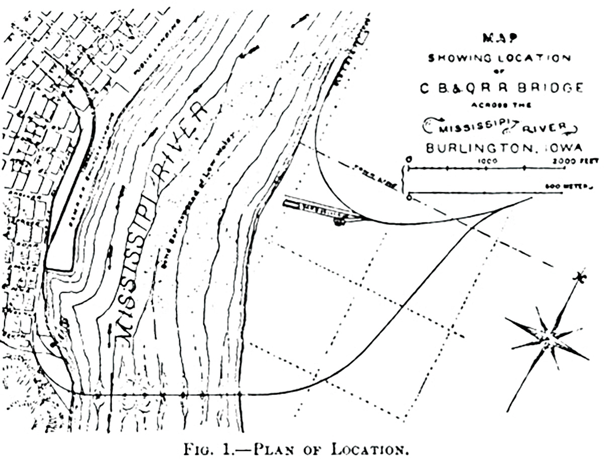
The channel of the river for 5,000 feet above the bridge and 3,000 feet below runs along the west bank in a direction for the most part parallel with the shore, which is rocky. The bluffs rise abruptly from the shore except at the site of the town, which is in an opening in the bluffs through which Hawkeye Creek flows. The river for two miles above and one below the bridge is confined to one channel, in which there is always a good navigable depth.”
The Chief Engineer was Max Hjortsberg, who started his surveys for a bridge as early as 1865 and determined that a bridge setting on piles was possible rather than the more expensive use of pneumatic caissons that were to be used by James Eads at St. Louis. Hjortsbert was born in Sweden. After working in England for a time, he emigrated to the United States in 1852. In 1854, he was named Chief Engineer for the Chicago, Burlington & Quincy Railroad. He located his bridge in the winter when the river was covered with ice, so direct measurements were possible rather than the need to resort to triangulation methods. A low-level bridge was the only type available for this site, given the low level of the land on the eastern bank of the river. That being the case, he had to meet the requirements of the 1866 Act for a low-level bridge that stated,
“That if any bridge built under this act shall be constructed as a drawbridge, the same shall be constructed as a pivot drawbridge with a channel draw over the main channel of the river at an accessible and navigable point, and with spans of not less than one hundred and sixty feet in length in the clear on each side of the central or pivot pier of the draw, and the next adjoining spans to the draw shall not be less than two hundred and fifty feet; and said spans shall not be less than thirty feet above low-water mark, and not less than ten above extreme high-water mark, measuring to the bottom chord of the bridge, and the piers of said bridge shall be parallel with the current the river.”
As seen by the plan, the line originally ended its track at a depot on the eastern Bank, where the cars would be loaded on a car ferry to the Iowa Shore. The selected bridge site was located about a mile to the south, where the river was narrower. The line had a sweeping curve to the right up to the river, then a bridge at right angles to the river, followed by a sweeping curve to the right and a new station at Burlington. The line then turned to the west through an opening in the bluff.
The bridge, as laid out by Hjortsberg from the west to east, was described by G. K. Warren,
“The bridge is approached from the west on an embankment with a curve of about 720 feet radius. The first span is 175 feet long from center of abutment to center of first pier-part of the span being over the land. The second span is 200 feet long. The trusses of these two spans are wider than those of the rest of the bridge to allow the curve of the approach to be extended on the bridge. The next span is a pivot draw 360 feet long overall, with two clear openings of 160 feet each; then there are 6 spans of 250 feet each from centers, and then trestling for a few hundred feet.”
The placing of the foundations was very innovative. It consisted first of driving wood piles and then cutting them off 1 to 5 feet below the original river bottom. This was followed by jetting away the sand around the pile tops and replacing it with crushed stone up to the level of the cut-off pile. Then the tops of the piles were covered with two layers of 12- x 12-inch timbers bolted together. Next, a wooden caisson, also built of 12- x 12-inch timbers, was floated into place. Masonry was then laid inside the wooden caisson, sinking it to a depth of 2 to 3 feet above the timber mat. Holes were drilled into the side of the caisson below the water level; the water that poured in sank the caisson onto the mat. Once the caisson was aligned properly with good bearing on the mat, the masonry was built up to a level above water, and the timber caisson’s sides were removed to be used again. George Morison, in discussing the Bridge, later stated, “One of the greatest features of the Burlington Bridge, as originally built, and as described by Mr. Hudson, the feature that has done more than any other to facilitate the building of bridges across the Mississippi, is the fact that they succeeded in doing work underwater without working underwater.”
As was then customary, Hjortsberg prepared a set of specifications and preliminary plans and sent them out to bridge Companies asking for their proposals and cost estimates. The Detroit Bridge & Iron Company was also building the Quincy Bridge just downstream and was awarded the contract for the superstructure. They proposed Whipple Double Intersection trusses for their fixed spans and a variation of the Whipple truss for the swing span. The top chords were cast iron, as were all the junction blocks, and the vertical posts were Phoenix Columns of wrought iron. The double panel diagonals and lower chord members were wrought iron loop bars. The swing span was operated by a steam engine mounted above the tracks and over the turntable.
Foundation work on the project began in January 1867, but due to ice and flooding, not much was done until March 1868. The last pier was finished for the swing span on March 3, 1868. The erection of the superstructure was very fast. On August 14, 1868, newspapers reported, “The iron railroad bridge, which has been in the process of construction across the Mississippi at Burlington since February 1867, by the Chicago, Burlington & Quincy Railroad Company, at a cost of over $1,500,000, was today tested, and pronounced completed. The first train passed over from Illinois to Iowa at 3:15 p. m….The successful transfer was honored with a salute of twelve guns and other manifestations of rejoicing.”
The bridge was test loaded on August 13, 1868, and witnessed by a select panel of engineers. Their report on the following day indicated that a load of 180 tons on the 250-foot span had a deflection of less than 2½ inches, and, when the load was removed, it returned close to its original position. Moving loads gave about the same deflection. The same load was applied to the swing span and gave deflections of less than a half inch. They also reported, “The draw was opened and closed, by hand power, several times for the passage of steamboats, while we were there, and once for our particular inspection, when it was opened in 31/2 minutes, and closed in a little over 4 minutes.”
Hjorftsberg wrote several years later, “all these works have been constructed to my entire satisfaction with respect to character of materials and workmanship.” What Hjorftsberg and the Detroit Bridge & Iron Company had done was to design and build the first all-iron bridge across the Mississippi River. In 1893, a two-track bridge by George Morison replaced the 1868 bridge. The new bridge has a swing span of 356 feet 6 inches, six 246-foot-long fixed spans, and two 70-foot plate girder spans opened for service. In 2011, the bridge was replaced with a 370-foot-long lift span, five fixed spans, and two plate girder spans.■