
New Life for the Berkeley Art Museum Building
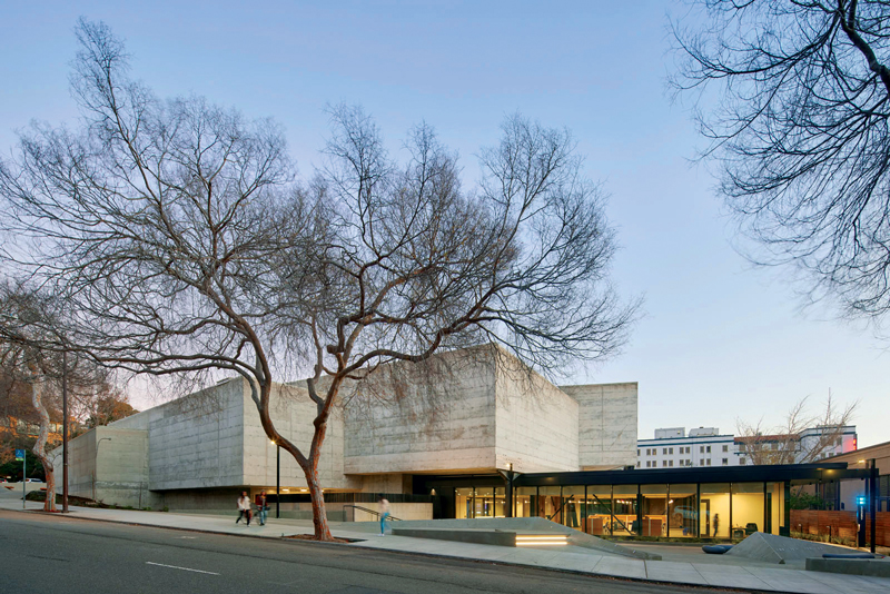
The Berkeley Art Museum (BAM) building was completed in 1970 and is an architecturally significant reinforced concrete building located on the University of California, Berkeley (UCB) campus. Originally designed by Architect Mario Ciampi, it is one of the most impressive examples of Brutalist architecture in the San Francisco Bay Area and is listed on the National Register of Historic Places. As a result of seismic deficiencies exposed by the 1989 Loma Prieta earthquake and subsequent studies that indicated the cost of a complete seismic retrofit would be similar to a full rebuild, the museum relocated to a new building in 2014, and the BAM building was left unoccupied. In 2016, the California Institute for Quantitative Biosciences (QB3) began a project to reuse the building as a full-service life sciences incubator. As a textbook example of successful adaptive reuse, the transformation of this landmark building incorporated a seismic retrofit into a complicated space, preserved the historic exposed concrete structure, replaced virtually all M/E/P/Fire systems, roofing, and skylights, and improved the building’s accessibility.
Building Description
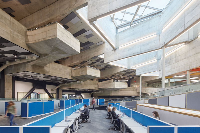
The existing structure is a complex non-orthogonal three-dimensional space. The signature architectural feature of the building is a large atrium, with five upper gallery levels partly cantilevered high above the atrium floor, all covered by a long-span roof with large skylights. In plan view, the upper gallery levels, each separated by a concrete wall, fan away from the center of the atrium in a nautilus-spiral shape, with walls running in the radial direction. There are no concrete walls in the orthogonal “tangential” direction. The upper galleries are terraced, and each level occupies a unique elevation separated with a five-foot vertical step. The upper gallery floors consist of two individual slabs (sandwich slabs) separated by a 3-foot interstitial space. Likewise, the concrete shear walls appear to be several feet thick but consist of two relatively thin walls with an interstitial space.
This unique layout allowed for the concealment of vertical and horizontal M/E/P/Fire systems, allowing the Brutalist concrete structure to be universally exposed throughout the building. Each upper gallery level is supported by the radial concrete walls on two sides, but the floor framing is rigidly joined only to one of the walls. The other wall was joined to the slab with thermal expansion joints. The expansion joints contributed to well-performing concrete with virtually no notable cracking after fifty years of service. However, these structural features – lack of a clear diaphragm, disjointed structure, and lateral system in only one direction – are the hallmarks of poor seismic performance. A 2001 temporary retrofit project added braces in the tangential direction, but only on one side of each upper gallery level. Therefore, each upper gallery level had lateral support only on two out of the four sides. The building sits on a foundation of reinforced concrete pier caps and drilled piers, with piers ranging from 18 to 54 inches in diameter and 15 to 85 feet of embedment. The 2001 temporary retrofit bracing is also supported on pier caps and drilled piers for consistency with the original foundation system.
Performance Objectives
UCB’s Seismic Safety Policy requires that buildings meet the Life Safety and Collapse Prevention performance objectives at BSE-R and BSE-C seismic hazard levels, respectively. The building was modeled in CSI Perform 3D and included the entire lateral system, part of the gravity system, and the existing pier foundation system. The 2001 temporary retrofit steel columns, braces, and concrete piers were also included in the model. A seismic evaluation based on the American Society of Civil Engineers’ ASCE 41 Nonlinear Dynamic Procedure (NDP) indicated that BAM did not meet UCB’s minimum requirements for existing structures. Significant damage was expected in the shear walls due to a lack of ductile detailing. A major seismic event could result in loss of gravity support at several locations, including the gallery expansion joints, indicating that a seismic retrofit was necessary.
Selection and Construction
There were several essential criteria in the selection of a retrofit’s structural scheme. The primary criterion was maintaining the building’s historical importance and character. Following the U.S. Secretary of the Interior’s Standards for Rehabilitation and Guidelines for Rehabilitating Historic Buildings and criteria from the historic preservation architect, the new retrofit elements should be clearly identifiable compared to the structure’s historic fabric. Since the interior and exterior exposed concrete was a character-defining feature of the building, a structural steel retrofit scheme was deemed preferable to concrete. Most retrofit elements are exposed in the finished condition, and it was important to the Architect that the retrofit elements be aesthetically pleasing. Careful attention was given to drawings and specifications to achieve a high-quality aesthetic for braces, gusset plates, bolts, welding finishes, and paint color. Several structural details were customized to add tapered sections and stiffener plates to achieve an aesthetic compatible with the structure added in 2001.
The existing concrete shear walls were very rigid. Rigid steel braced frames were selected to achieve drift compatibility between the existing and new structures. A Buckling-Restrained Braced Frame (BRBF) system was used to allow for fine-tuning the stiffness of the braced-frame system; the core area of each BRB could be increased as required to match the stiffness of the corresponding concrete wall. The BRBF system was added to each upper gallery level in both the radial and tangential directions, forming a complete four-sided lateral system for each level. Introducing the retrofit braced frames into the analysis model significantly reduced the expected drift of the building, reducing strain in non-ductile concrete elements, limiting damage to the rest of the structure, and meeting UCB’s seismic performance requirements. The final BRB core areas were determined after several iterations of computer analysis, and the analysis confirmed compatibility between the existing and new structural elements.
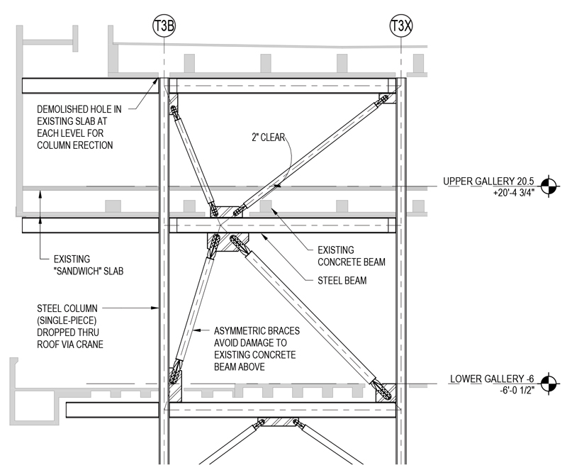
Layout and constructability of the new retrofit braces, beams, and columns were critical for the project’s success, both for optimizing the architectural layout of a challenging adaptive-reuse project and limiting damage to the existing structural components in the building. Some structural demolition was necessary to erect the new retrofit steel. The full-height steel columns had to punch through six structural slabs (two sandwich slabs and two regular slabs) between the roof and the foundation, and damage at each level had to be carefully considered. Rigorous field verification confirmed that the existing structure was primarily built following the 1970 as-built drawings, and structural members, connections, and demolition extents were detailed to account for tolerances from the original construction and the needs of the steel erector. Early involvement from the Contractor helped generate a positive design feedback loop between the needs of the new structure, the Contractor’s means and methods, and the demolition of the existing structure as required for steel erection.
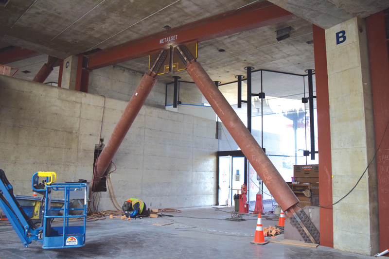
Columns were located within 2 inches of the existing concrete walls, and column splices would have involved blind-side CJP welds, which posed numerous challenges for welding and inspection. To avoid this, an erection sequence was selected in which column base plates and 4-foot-tall column stubs were installed, after which the remainder of the approximately 60-foot-long column was dropped in a single piece through the roof, upper galleries, and other floors. Tight coordination of demolition and new steel allowed for demolition that was barely larger than the cross-section of the steel column. A similar constructability modification involved using non-symmetric braced frames to avoid existing structural gravity elements at the upper gallery levels. The non-linear analysis model was used to evaluate the steel elements for forces resulting from this asymmetry. Field verification was critical to avoid costly and schedule-impacting clashes during steel erection with tight clearances between existing and new structures. The importance of field verification was emphasized through all communications with the Contractor during project meetings, RFIs, and shop drawing reviews. A collaborative team spirit was critical to the success of this project.
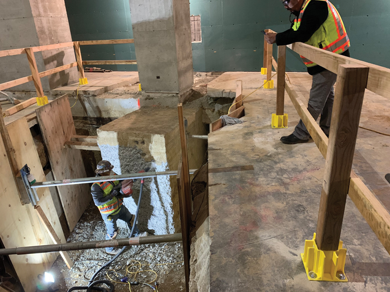
At the foundation level, the new steel columns do not align with the existing drilled piers. Early in design, it was determined that new deep foundations would be infeasible due to tight-overhead restrictions in the existing basement levels. To support the new steel columns, a transfer foundation system was designed in which a large, sub-grade concrete transfer beam spanned between existing drilled piers to support the new steel columns.
Conclusion
The seismic retrofit, along with upgrades to accessibility and mechanical systems, has extended the life of this landmark building far into the future by repurposing a disused but highly treasured building. The structure now houses research aimed at making the world a better place. The goal of linking professional, cutting-edge researchers with UC Berkeley students is to encourage collaboration among bright minds and inspire the next generation to achieve the impossible. The parallels between the current use as a research facility and the original use as an inspirational art museum are evident.■
Project Team
Owner: QB3 / University of California Berkeley
Structural Engineer: Forell | Elsesser, San Francisco, CA
Architect: MBH Architects, Alameda, CA
Contractor: Plant Construction, San Francisco, CA