
High-Strength Reinforcing and Performance-Based Design
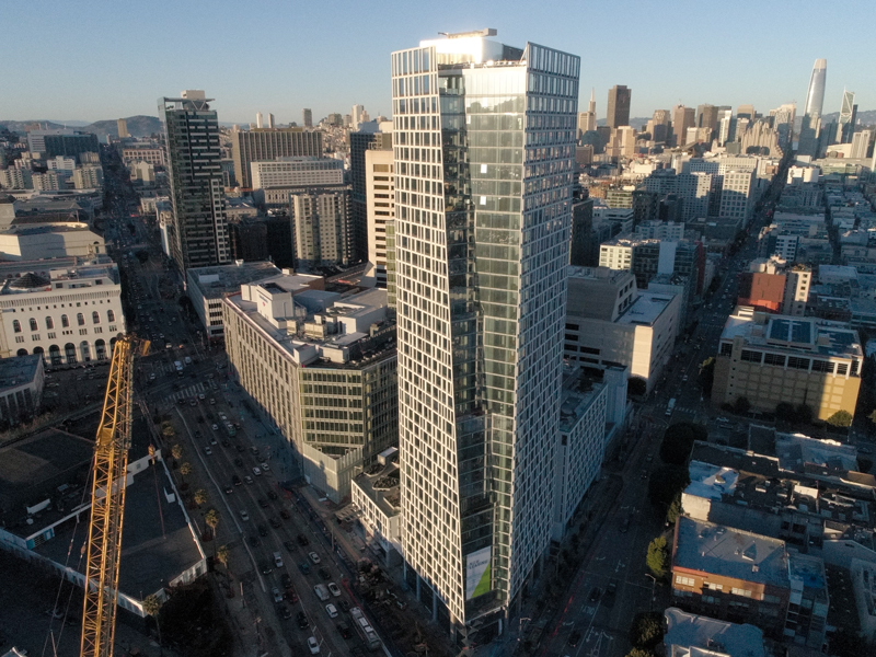
Located in the 14-square-block downtown redevelopment area and two blocks from City Hall, Fifteen Fifty and 49 South Van Ness stand literally at the center of San Francisco.
A portion of the two-building project, the 16-story steel-framed office tower (49 South Van Ness), is home to the City’s Department of Building Inspection, which set a high-performance standard for its new home: a Category III building to increase seismic resiliency. Add in the 39-story concrete residential tower (Fifteen Fifty) – which ties into an at-grade alley structure with the office tower – along with a high-water table and the region’s high seismicity. This results in a considerably large and complicated puzzle to solve.
With 780,000 gross square feet in the residential tower and 460,000 for the office tower, Fifteen Fifty and 49 South Van Ness amass over 1.2M square feet of constructible area. To keep costs low relative to the project’s size and quantity of materials, DCI Engineers – the SEOR for both buildings – opted to pursue a Performance-Based Design using 80 ksi high-strength vertical reinforcement in the concrete shear walls – the first high seismic project to do so in the United States. As a result, the amount of reinforcement was reduced, and a more robust design was provided.
The Project Pieces
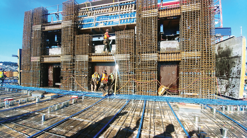
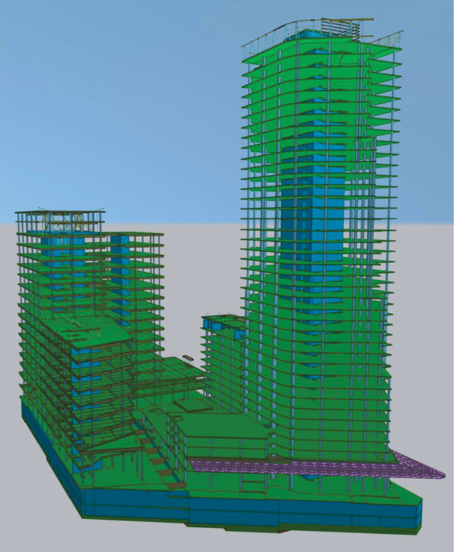
The residential building is an all-concrete tower with a central concrete core wall lateral system and two separate blade walls in the two wings of the building. Post-tensioned slabs are used above grade with mild reinforced slabs at and below grade. The office tower is a steel-framed structure above grade and mild reinforced concrete below grade with a concrete shear wall lateral system in the tower and another blade wall in the wing. Both buildings are tied together at grade and for the two levels below grade. This connection required extensive analysis of force transfer between the buildings at this level. Also, a continuous mat foundation ties both buildings together and resists a full story of hydrostatic pressure. The continuous mat and connection of the two buildings eliminated any bathtub waterproofing concerns and made for a more economical project by eliminating interior basement walls to separate the two buildings.
Pushing Innovation Forward
A performance-based seismic design approach was initially pursued simply because the residential tower height is over 240 feet tall, which is typical for high-rise residential towers in seismic regions. This alone saves on material.
But that approach provided an additional design assist when the City of San Francisco Department of Building Inspection requested that its new headquarters building remain serviceable under an extreme seismic event. The desire was to allow the facility to be used during emergencies to help bring critical functions of the City government back online faster. Since the team was already using a performance-based design approach, it was determined to design to Risk Category III (typically a 25% increase in forces) to increase the resilience while maintaining the same cost as a Risk Category II building.
Code designs do not require an explicit check of all the concrete strains, reinforcing strains, and building deformations for a maximum-considered seismic event. In contrast, a performance-based design approach requires that these are checked and met. It also grants the freedom to explore deviating from strict code rules. In this case, DCI pursued the use of higher Grade 80 vertical reinforcing in the concrete shear walls when the code limit at the time was 60 ksi. This provided for an efficient residential tower and a more resilient Risk Category III office building for the cost of a Risk Category II building.
Grade 80 Approval
It is important to note that a performance-based design approach does not guarantee immediate approval of any concept. As the name suggests, a proposed concept must perform adequately to be approved. The simplest way of proving performance is through physical tests. An example is to use past tests to model non-linearity in the analyses. The performance-based design process also requires a panel of national experts to review and approve the design. Typically, a practicing engineer, a professor who does research in the field, and a seismologist are all required to review the project. The analysis, calculations, and any deviation from the code must be rigorously reviewed and approved by the peer reviewers and the building department.
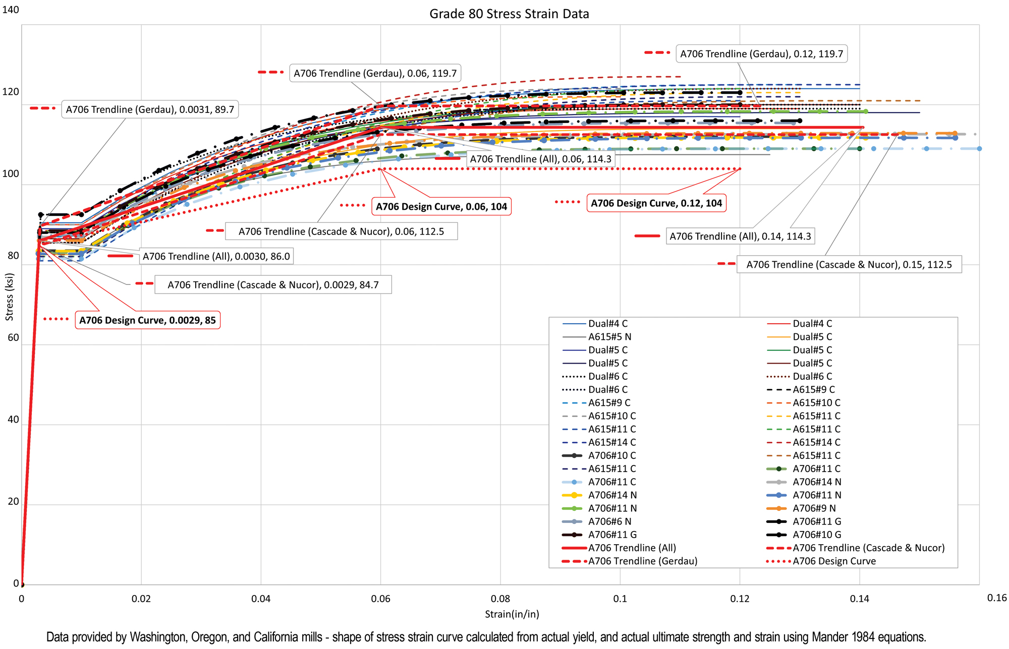
Grade 80 reinforcing was already being produced during the project’s early design. Still, it was mainly used for projects in non-seismic areas or large foundations where the inelasticity of the material was not a concern. Therefore, additional research by the design team was required to evaluate the viability of this solution. First, information from several manufacturers of Grade 80 reinforcing throughout the west coast was collected. Next, actual yield and ultimate strengths along with elongations were plotted, from which a lower bound estimate of the minimum yield that any producer could achieve along with the approximate overstrength (ultimate divided by yield) was determined.
Determining reinforcing properties was only part of the picture. Reinforcing in tension is governed by yield and tensile strength. However, reinforcing in compression is governed by how often it is supported along its length – or in structural terminology, how often confinement reinforcement is spaced along its length. The existing American Concrete Institute code at the time, ACI 318-14, Building Code Requirements for Structural Concrete and Commentary, had governing minimum limits of six times the bar diameter or six inches, whichever was smaller. But those were based on Grade 60 reinforcing tests. So, the team needed to figure out a way to justify the confinement reinforcing spacing for the higher Grade 80 reinforcing.
As there was not much research on low cycle fatigue tests of Grade 80 reinforcing, the team decided to require tests for the project to prove it would work. The decision was made to reduce the confinement spacing from six times the bar diameter to five times the bar diameter to achieve the required results.
Low cycle fatigue tests on all vertical Grade 80 reinforcing were required in the project specifications for the actual mill certs submitted for the project and all bar sizes used.
Low Cycle Fatigue Testing
As a result of these requirements, the team needed to wait until just before construction to get results on the tests. This was nerve-racking for the team as the entire analysis assumed that the test results would pass. The whole team took a leap of faith.
As a requirement for a passing grade, the tests needed to achieve at least 1.5 times the number of cycles exceeding the mean yield strain for the non-linear analysis. All mean strain results were below the acceptable limits of +1% in tension and 0.5% in compression, for a total strain range of 1.5%. The loading protocol was determined by taking 1.0 times the tensile and compressive acceptance strains. A critical strain gage for each Perform 3D tower model was selected based on the maximum mean strains (modeled gage length was approximately 6 feet). The time history results for the critical gage were plotted, and the number of strain cycles above yield was recorded for each ground motion.
Worst case cycles past yield occurred in the residential tower model, with a total of 11. Taking the product of 1.5 and 11 yields a minimum of 17 cycles to failure for the testing criteria. For the project specifications, 30 full cycles were conservatively used as the requirement. Previous prediction models estimated the team could achieve 40 cycles to failure, so using 30 as the criteria seemed reasonable.
Bar sizes of #8, #9, #10, and #11 were used and tested. Actual results for ASTM A706, Grade 80 reinforcing used in the project produced test results of 175 to 275 cycles depending on the bar size, which exceeded expectations.
Closer to Sustainable Resilience
In the end, the shear wall vertical reinforcing is a mixture of Grade 60 and Grade 80. Spacing and size rules sometimes governed the minimum reinforcing area for higher stories where demands are lower, and Grade 60 was more appropriate. Grade 80 reduced shear wall congestion on the lower stories and made for easier construction of both buildings.
Higher-strength reinforcement reduced the amount of reinforcing steel required in the shear walls while providing the same level of resilience and ductility. The results included a reduction in vertical reinforcing in many stories by 25%, thus saving the project more than $1M worth of material costs.
The low cycle fatigue testing that was performed on the Grade 80 reinforcing for this project and the new rules developed for confinement tie spacing as a result of the tests have resulted in new confinement rules that are now incorporated into ACI 318-19 for Grade 80 vertical reinforcing in shear walls – a new standard moving forward.
The introduction of higher-strength reinforcing in this project puts the industry one step closer to meeting the goals of the Structural Engineers 2050 Commitment Program. It provides new tools to help reduce the building industry’s carbon footprint.
Structural engineers can make a difference in creating sustainable and resilient buildings on a large community scale, one small innovation at a time.■
Project Team
Owner: Related California, City of San Francisco
Structural Engineer of Record: DCI Engineers
Architect (Fifteen Fifty): SOM and HKS Architects
Architect (49 South Van Ness): SOM
General Contractor (Fifteen Fifty): Build Group Inc.
General Contractor (49 South Van Ness): Pankow
Geotechnical: Langan Engineering and Environmental Services, Inc