
The Reimagined Arkansas Museum of Fine Arts to Open in 2023
MacArthur Park in Little Rock, Arkansas, opens in the spring of 2023 with a significant update to one of its most familiar structures. The reimagined Arkansas Museum of Fine Arts (AMFA), formerly the Arkansas Arts Center, is planning a grand opening after more than three years of construction. The new AMFA is one of the most dramatic updates to this ever-changing museum.
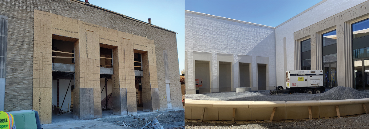
Opened in 1937, the original Museum of Fine Arts was an unreinforced brick masonry building with approximately 10,000 square feet, housing mainly gallery space. In 1963, the first addition to the museum was made, significantly expanding the square footage, and the Museum of Fine Arts was then recognized as the Arkansas Arts Center. The 1963 addition included what is now the art school, lecture hall, and theater. Between 1963 and 2000, two more additions were made to expand administrative offices and space for the Children’s Theater department. Finally, in 2000, new gallery space was added to supplement the original building’s gallery. Over the last 60 years, the additions transformed the original Museum of Fine Arts. The historic limestone art deco façade was completely enclosed during the 1982 expansion and was incorporated as a feature of one of the building’s new interior galleries. In 2023, AMFA is set to reveal another stunning transformation, reinforcing its presence in Little Rock. The familiar face of the restored museum’s façade will welcome the public back to the museum once again.
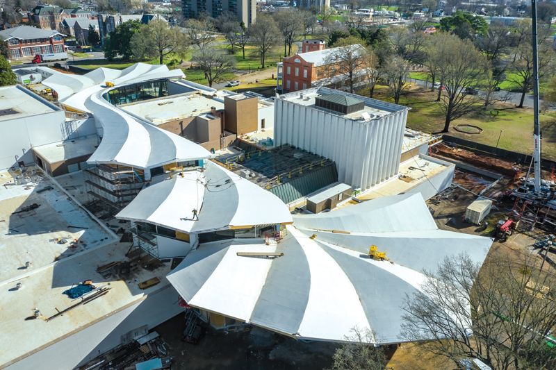
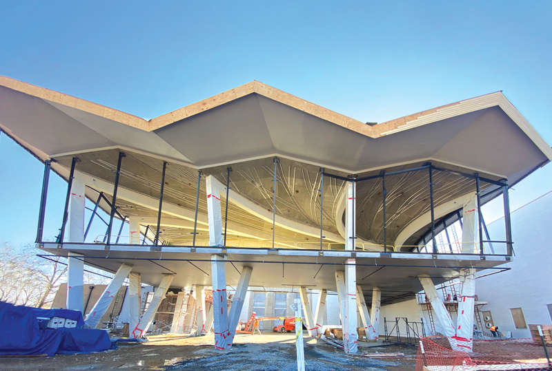
The project’s centerpiece is a new concrete structure with a light and organic folded plate roof, which cuts through the existing facility and creates new circulation and rational links between various functions.
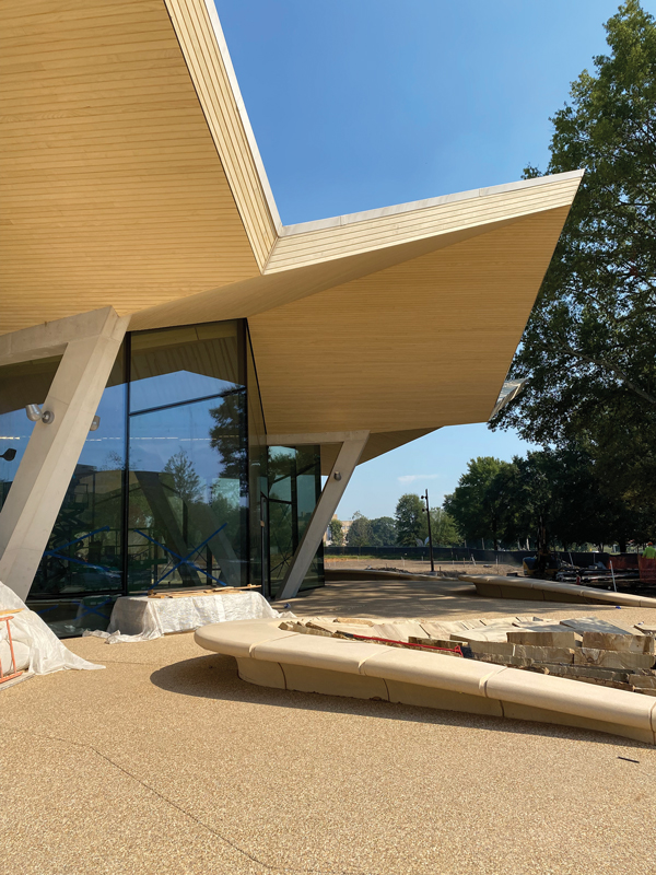
The folded plate roof structure and new clerestories open the interior of the museum complex to natural light and extended sightlines. It integrates new construction with renovated spaces on either side and connects the museum’s exhibition, education, and performing arts programming. The Courtyard Entrance, located at the north end of the museum, is a glass-enclosed elevated structure above an open courtyard, which serves as a venue for events and a space for visitors to gather. The Park Entrance at the south end is an indoor-outdoor restaurant with floor-to-ceiling windows opening onto the surrounding terrace.
Shear walls and sloping columns support the folded plate roof structure. The shear walls are partially curved to follow the roof’s geometry and serve as part of the lateral system. A key decision was made to structurally isolate the new concrete structure from the existing steel buildings, thus allowing the design team to use a more favorable R factor for the seismic design of the concrete structure.
Little Rock is located in a moderate seismic zone, which controls the structure’s lateral design. The site has favorable soil conditions, which allowed the building to be classified as Design Category C. Due to the highly irregular shape, a Response Spectrum Analysis was performed to accurately capture the new concrete structure’s seismic response. The curving shear walls served as the lateral system for the concrete structure and were modeled in SAP using straight, vertical segmented shell elements to generate the large radius curves. The shear walls were designed outside SAP using section cuts to extract in-plane shears and shell stresses to capture the out-of-plane behavior. Any in-plane shear within the walls generated weak axis bending due to the curving geometry, and the shell stresses allowed the design team to capture this component of the shear wall design.
The new folded plate roof is an 8-inch concrete slab with mild reinforcement supported on sloping columns spaced approximately 30 feet apart in the transverse direction and up to 90 feet apart in the longitudinal direction. The folded plate also cantilevers up to 25 feet beyond its supports. The height differential between the ridges and valleys varies up to 12 feet to create each fold. The roof structure is composed of three distinct segments separated in elevation while spanning the 400-foot site.
One of the early challenges during design was developing a process to model the organic folded plate roof analytically so it could be easily modified as the design evolved. The architect modeled the roof in Rhino, and the geometry included the folds, the overall roof sloping for drainage, and gentle bowing between ridges and valleys. Early in the design phase, the design team collaborated with Studio Gang to efficiently translate their Rhino model into a SAP model using Grasshopper. This translation was developed in-house by Thornton Tomasetti’s R&D incubator, CORE, and was tailored to this specific application. The Grasshopper translation created shell and frame elements in SAP that matched the architectural geometry. The shells were meshed during the translation because automatically meshing larger shell elements in SAP would have increased model run times and added complexity to the analysis. In addition, due to the number of shell elements, any design changes to the geometry required a full retranslation of the new Rhino model due to the impracticality of manually implementing the geometry changes. Establishing an efficient translation process early in design allowed the structural team to incorporate changes quickly throughout the design process.
The design of the unique, organic structural form required an understanding of folded plate behavior and the application of basic reinforcing principles to complex geometry. The striking geometry is actually the key to the behavior of the structure. The folded plate behaves like a truss longitudinally between supports. The ridge is the top chord under compression, and the valley is the bottom chord under tension. When the roof cantilevers, the truss tension and compression chords reverse, and the reinforcement must transition to accommodate this change in stress. In the transverse direction, there is an accordion action for both gravity and lateral loads. Under gravity, the folds naturally tend to flatten out. Under lateral loads, the folds compress and expand like an accordion. This longitudinal and transverse behavior became more complex due to the organic shape.
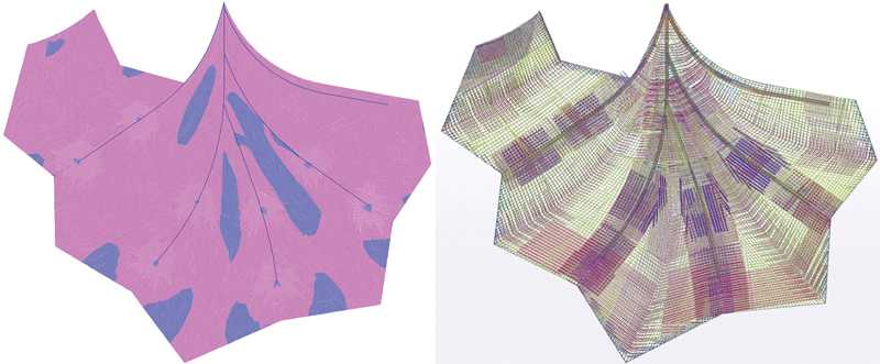
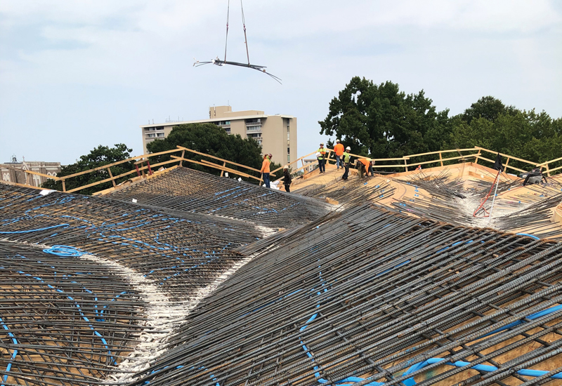
Reinforcement of the unique shape required an established rebar layout early in the design process. The ridges and valleys set the direction of the longitudinal reinforcement. As the ridges and valleys turn and meander along the roof length, so does the longitudinal reinforcement. As multiple roof panels merge or diverge, the rebar in the slab is detailed to follow this geometry. Similarly, the transverse reinforcement was detailed always to be perpendicular to the ridge and valley, which meant very few bars were ever parallel. The local axes of each shell element were oriented to follow the reinforcement and output stresses in the appropriate directions to capture this reinforcing scheme. The structural team applied a uniform reinforcement mat throughout the slab and used this as a lower bound for the shell stresses. Any value above the lower bound required additional reinforcement, detailed on the structural drawings using a visual review of the shell stresses in the model. This visual review was needed because no automated tools were available for rebar design for such a complex shape.
The Courtyard Entrance structure at the north uses sloping rectangular columns supporting the elevated slab (that serves as a gathering space) and the folded plate roof. The columns form a V shape under the elevated slab, which allowed the design team to cut down on the slab spans and eliminate the need for PT on the project. Above the elevated slab, individual legs of the V extend above to support the roof at the perimeter and create an open space with no interior columns. This was possible due to the ability of the folded roof to span long distances without supports. Sloping V columns are also used to support the roof of the Park Entrance at the south; however, their shape changes over their height. The shape is similar to a flattened V at the base of the columns and an elongated pentagon at the top of the column. This morphing shape is similar to columns designed by renowned Italian engineer and architect Pier Luigi Nervi and posed a challenge to the design team in understanding the constructability of the longitudinal reinforcement that ran through the columns. The team created 3-D models during design to understand how bars transition and move throughout the column as it changes shape. A reinforcement scheme was derived to allow continuous longitudinal bars with limited splices over the column height. As a result, all sloping columns remain architecturally exposed, which allows park and museum visitors to interact directly with the structure.
The contractor for the project was a joint venture between Nabholz, Pepper, and Doyne. Pepper Construction self-performed the folded roof concrete work. Several formwork options were explored for the construction of the folded roof structure, including CNC-milled forms. To create the intended geometry, the contractor ultimately chose to use custom wood trusses 12 inches on-center with plywood sheeting. To accommodate the formwork scheme and simplify constructability, the design team tweaked the analytical geometry of the roof, which resulted in increased rebar in some locations.
Detailing the rebar for the complex roof geometry required extensive coordination between the structural team, Pepper’s self-perform team, and the rebar detailer DNA Detailing & BIM. The reinforcement drawings were shown in 2-D on the structural design documents and supplemented with details to convey how the bars would lay out in 3-D. The detailer developed a Tekla model laying out the rebar in 3-D to validate the design intent. The Tekla model allowed the detailer to identify zones of high congestion and areas where the rebar detailing would be difficult, such as locations where multiple roof panels merged. The structural team made suggestions and rules for the detailer to follow to simplify the rebar layout while providing the required strength for the roof. The 3-D Tekla model was crucial during construction administration because it allowed all parties to confirm the bar layout before submitting shop drawings. The coordination between the structural team and concrete detailer was so successful that there was just one RFI related to bar placement in the field throughout all three roof placements.
The project presented several structural challenges in addition to the folded plate roof structure. Slicing through a collection of existing buildings constructed over a long period meant their lateral systems could be impacted. A review of the structural drawings indicated that the majority of the remaining existing building components were laterally stable, except for a one-story art school that had to be laterally connected to new shear walls.
The new gallery space on the second floor next to the main entrance to the north saw significant structural modifications to the existing structure and required creative solutions. The laterally independent structure was initially designed as a tall single-story space with a stepped roof. The new design added a second level to create the gallery space, and a flat roof was created by raising the existing stepped roof in some areas and lowering it in others. The design team was able to re-use and maintain, in place, many of the structural elements of the existing gallery. The original gallery was designed as a moment frame structure with tall columns designed to resist lateral loads. The structural team added new braced frames converting the structure from a moment frame to a braced frame system. This allowed the reserve capacity of the columns to be used to support the additional floor. In addition, the new floor also reduced the unbraced length of the tall columns, further improving their ability to support new gravity loads. Existing footings were checked and enlarged to support the new gallery loading where needed. Micropiles were used to increase the capacity of the footings at the new braced frame locations.
The current design included several changes to the original 1937 Museum of Fine Arts. First, part of the existing second floor was removed to create a double-height atrium when guests enter the museum – this required new lateral bracing for the unreinforced masonry piers that make up the entryway. In addition, new openings were cut in the museum’s walls, which impacted the structure’s lateral capacity. The structural team tracked the change in demand and capacity to confirm it stayed within the International Existing Building Code limitations for renovations to existing structures.
A prominent change to the building was the restoration of the original façade. The exterior walls are four brick wythes thick, and the exterior layer required replacement for aesthetic reasons. Since the building uses the exterior walls as part of the gravity and lateral system, removing brick impacts the load-resisting capacity. The structural team developed a sequence of removing and replacing the brick to limit the change in capacity in the temporary state and maintain the wall’s capacity in the final state.
The reimagined AMFA has dramatic changes both inside and out. The folded plate roof creates an incredible presence in MacArthur Park, which can also be felt in every room of the museum while maintaining the historic integrity of each addition. The world-class space will give the client and Little Rock a platform to showcase everything they offer for years to come.■
Project Team
Structural Engineers: Thornton Tomasetti, Inc.
Façade Engineers: Thornton Tomasetti, Inc.
Architect of Record: Studio Gang
Associate Architect: Polk Stanley Wilcox
Contractor: Nabholz Construction, Pepper Construction, and Doyne Construction Co.
Concrete Contractor: Bass Concrete
Folded Plate Concrete Contractor: Pepper Construction
Rebar Detailer: DNA Detailing & BIM
Steel Fabricator: W&W Steel | AFCO Steel