
Historic buildings draw us in with their character and sense of history. Cracks and imperfections are part of the appeal. But what happens when the quirks are not just superficial but indicators of significant structural distress? For Central Standard Craft Distillery, a Milwaukee-based company that purchased an 1874 building, the answer was to implement a top-to-bottom structural retrofit that would preserve the charm while also making the building safe to occupy. In January 2020, national interdisciplinary design firm HGA joined the mission to renovate the 16,000 square-foot, three-story building to create space for a bar, restaurant, tasting room, events space, and rooftop patio to promote Central Standard’s growing business. Originally designed by renowned Milwaukee architect Edward Townsend Mix, the building’s condition had worsened over the years due to foundation settlement and deficiencies in the original engineering design. Floors that were originally flat now sloped as much as 15 inches over 60 feet, while brick walls leaned to the west by as much as 6 inches per story.
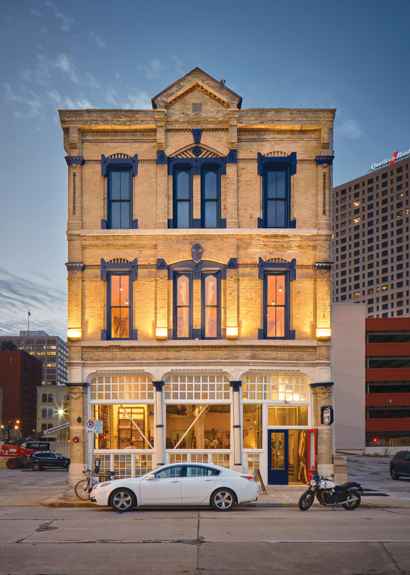
The structural retrofit would include micropile-supported foundations, masonry shear walls, steel bracing, and plywood diaphragm reinforcement. No attempt was made to lift and straighten the building. Instead, the effects of the leaning walls and sloping floors would be accounted for by HGA in the structural design. Finding locations for the new shear walls and bracing was difficult as the architectural plan called for open spaces with the existing brick and timber framing exposed prominently. The engineering team’s solution for concealing the new masonry shear walls was to integrate them into the stair and elevator enclosures. Where visible repairs were inevitable – such as the steel X-bracing at the windows of the street façade (Figure 1) – HGA chose solid bar bracing over steel tubes to minimize the visual impact. Installation of the structural repairs by the general contractor, Gardner Builders, also needed to be sensitive to the requirements for historic preservation. For example, existing wood flooring was carefully removed so it could later be reinstalled over the plywood diaphragm reinforcement.
Starting at the Bottom
To determine if foundation stabilization would be necessary, HGA excavated a test pit in December 2020 to examine the original foundations and assess their condition. They discovered that in 1874, the builders used a system known as timber grillage, where brick and stone walls were built directly on a grid of timbers – similar in size to railroad ties but placed tightly together and oriented in two layers in alternating directions (Figure 2). Timber piles were not found in the test pit or any subsequent excavations. (It is the author’s experience that timber pile foundations are encountered more frequently under similar buildings in this area.)
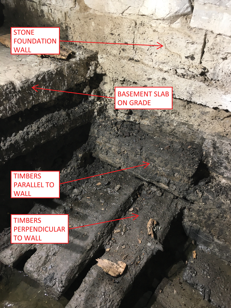
Groundwater was encountered only 12 inches below the top of the basement slab, requiring the pit to be dewatered before the timbers could be inspected. The groundwater relates to the natural topography at the time of construction. In 1874, the project site was located at the transition between solid ground and a marshy area that was being infilled to create what is now called Milwaukee’s Historic Third Ward. It may seem counterintuitive that untreated timbers can be used for foundation systems in wet areas. Yet, as long as the timber sections remain fully submerged, oxygen is driven from the wood fibers, and the oxygen-loving organisms that cause decay cannot survive.
The gradual lowering of the water table in Milwaukee over the past 150 years has caused many timber foundations in the area to dry out and experience decay, along with accelerated settlement. In these cases, foundation retrofit is typically cost-prohibitive, and demolition generally follows. The author feared that decay might be the cause of the settlement at Central Standard’s project. The test pit, however, revealed intact timbers. Instead, soil borings taken in January 2021 pinpointed the actual cause of the settlement – consolidation of the marshy, organic soil. Thus, the timber grillage foundation system was functioning as originally installed. However, its original design was flawed, and the organic soils could not support the weight of the building without excessive settlement.
A Study of Geometry
Uneven vertical settlement of the foundations initiated a westward tilt in the building’s walls and columns. At the south façade, as shown in Figure 3, the horizontal displacement was noted between the sidewalk elevation and the top of the first story. The structure is primarily a rectangular brick box, except for the lower part of the street façade where no shear wall or bracing exists. The author imagined a conversation held in 1874 between the architect and the builder to discuss which was more important – building integrity or windows. The windows were obviously judged to be more critical, resulting in an incomplete lateral system. This needed to be addressed by HGA.
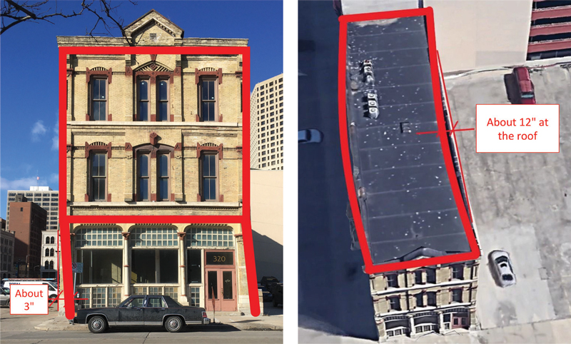
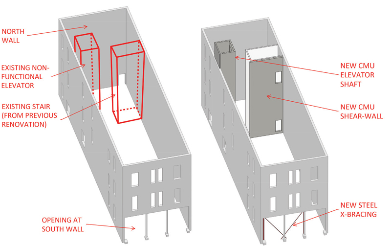
In addition to the displacement at the south façade, horizontal displacement also occurred between the north and south walls, as shown in Figure 3. Calculations by HGA revealed that the existing tongue-and-groove subfloor was severely under-designed in terms of diaphragm strength and stiffness and could not resist this horizontal movement. A stair was added in a 1990s renovation to meet fire-safety requirements, worsening the situation and further weakening each floor diaphragm’s integrity (Figure 4).
The out-of-plumb condition of the existing brick walls was a significant concern. The massive weight of the leaning walls generated horizontal forces that exceeded the design wind loads. Calculations revealed that the building’s flawed lateral system could not even resist the required wind forces, so it was a mystery how the building had survived for so many years in this condition. It became evident to HGA that significant upgrades to the lateral system would be needed.
A Path Forward
The combination of wind load and horizontal forces related to the leaning walls meant that most components of the upgraded lateral system would be pushed beyond the range of what is typical for a building of this type and size. To increase diaphragm strength and stiffness, ¾-inch plywood was applied over the existing subfloor at each level. With a shear demand exceeding 1,000 pounds per foot, blocked diaphragm values with tight nailing patterns were required. Where the existing timber sub-floor was thick enough, HGA justified that it could serve as the blocking without the need to install 2x members under the floor. At other locations, the author detailed stapled sheet metal blocking, which could be installed entirely from the top side of the floor. Diaphragm chords were created at the long sides of each floor using laminated veneer lumber (LVL), purchased in 42-foot lengths to minimize splices.
As shown in Figure 4, an existing stair and non-functional cargo elevator blocked diaphragm access to the north wall. Although the elevator was being upgraded to a modern system, it needed to remain in the same location. Similarly, relocating the stair would not be practical. HGA’s solution was to introduce a concrete masonry unit (CMU) elevator shaft and an additional shear-wall tight against the existing stair. All CMU walls were heavily reinforced – sometimes with two #7 bars in a single cell – requiring mechanical bar couplers. Excavations were required under the basement slab to install micropile-supported foundations for support of the new shear walls (see next section). Carpenters modified the existing framing at each level to create space for the shear walls.
The last piece of the structural puzzle was to address the addition of bracing at the large opening in the south façade. Solid steel bars, 2¾ inch in diameter, were chosen along with matching clevises and turnbuckles to accommodate the horizontal forces while minimizing the braces’ visual impact. An HSS 10x6x½ was used at the top of the first floor to facilitate the connection between the braces and the existing brick wall above. The braces were anchored to a concrete grade beam in the basement, again supported by micropiles.
What To Do with the Foundations?
With a plan worked out to address deficiencies in the lateral system, HGA shifted its focus back to the foundations. It was always known that the new walls and bracing would require concrete grade beams supported by micropiles but deciding what to do with the existing foundations was the subject of much discussion. HGA presented an option to the building owners, including a full retrofit of all timber grillage foundations using micropiles. This option, however, was judged to be cost-prohibitive and incompatible with the project schedule. Despite concerns about differential settlement between existing and new foundation components, the project team decided that foundation strengthening should occur only at the steel bracing and new masonry walls.
This decision was judged to be acceptable for three main reasons. First, the exposed brick walls were in remarkably good condition and showed no signs of accelerated settlement or distress in recent years. The condition suggested to HGA that vertical and horizontal displacement had occurred at a slow and consistent pace. Secondly, though the engineering design of the timber foundation system was deficient, the timbers themselves were intact, and the system was functioning as initially constructed. Thus, any future settlement would follow the established trend. Finally, the last factor that influenced HGA’s strategy for foundation repairs was the intended life span, established by the building owners to be 20 years of occupancy beyond the completion of renovations.
Though the team believed that the structural retrofit would lessen the potential for further settlement and displacement, they adopted a belt and suspenders approach by designing the new lateral system to accommodate 20 years of future westward lean. Future movement was estimated to follow the same trend as the displacement that had already occurred. A survey program was also established to monitor the position of the leaning walls at regular intervals over the next 20 years.
The Deep Foundation System
A micropile is a reinforced grout column created by advancing a cutterhead into the soil while simultaneously injecting a high-pressure cementitious mixture. Design and installation of the micropiles were performed by a specialty foundation contractor based on design parameters provided by the geotechnical engineer. A total of 45 micropiles were installed, each supporting 20 tons through both skin friction and end bearing at depths of up to 80 feet below the basement slab. Reinforcement for each micropile was provided by a 1½-inch diameter hollow steel bar, which also served as the shaft for the cutter head and a conduit for the grout pumped to the bottom of the excavation during installation.
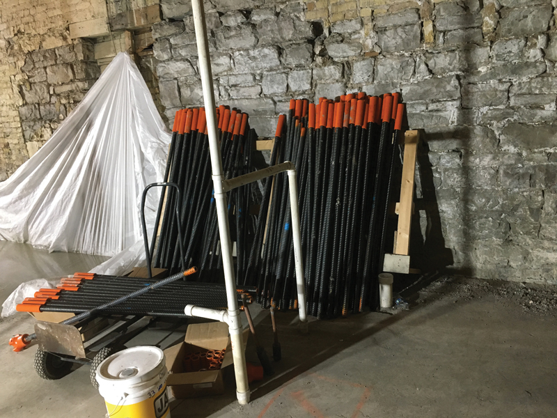
Micropiles were selected for the deep foundation system primarily because they can be installed with minimal overhead clearance. The hollow steel bars were supplied in 4-foot lengths (Figure 5) and spliced using threaded couplers.
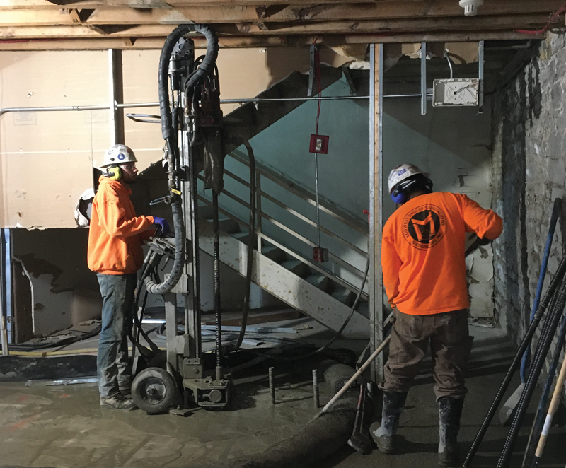
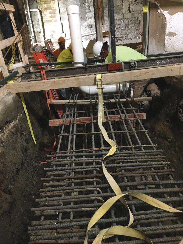
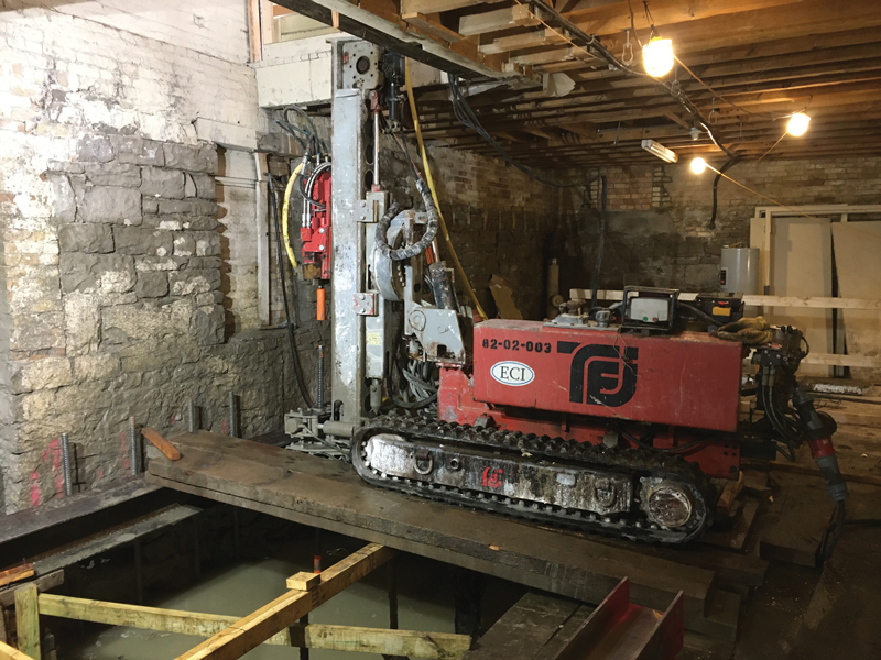
Advancing the cutter head into the soil required a counteracting force on the top side. In most cases, the existing basement slab was used as the anchor for a portable installation rig. Holes were first core-drilled through the existing slab at the micropile locations, and the rig was then bolted to the slab above each location in turn. Figure 6 shows this process. When all micropiles in an area were completed, the existing slab was removed. Next, a concrete grade beam was constructed around the exposed tops of the micropiles (Figure 7). At the location of the new elevator pit, where no slab was available for anchorage, a heavier track-mounted drill unit was used (Figure 8). This machine’s self-weight counteracted the upward reaction caused by the micropile installation.
Conclusion
HGA’s structural retrofit was critical in transforming a neglected, historic building into a vibrant – and safe – local destination. A successful outcome was achieved through practical structural solutions as well as respect for the historic nature of the building. The building’s unusual shape was not adjusted or straightened; rather, it was preserved in its current condition, with the leaning walls accounted for in the upgraded lateral system. The project demonstrates that adaptive reuse of a historic building can be cost-effective and schedule-friendly while delivering authentic charm and character that would be difficult to reproduce in a new build. Please perform a structural inspection of your own (during happy hour, of course) if you are in the area.■
Project Team
Owner: Central Standard Craft Distillery
Architect and Structural Engineer: HGA, Milwaukee, WI
General Contractor: Gardner Builders, Milwaukee, WI
Geotechnical Engineer: Terracon Consulting Engineers and Scientists, Milwaukee, WI
Micropile Contractor: Midwest Drilled Foundations & Engineering, Waukesha, WI
Structural Steel Supplier: Duwe Metals, Menomonee Falls, WI
Project Manager: Jones Lang LaSalle