
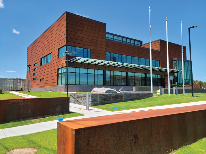
The new Massachusetts Bay Transportation Authority (MBTA) Iron Horse Park Operations Control Center (Figure 1) is designed to house dispatching and administrative operations for the MBTA north-side commuter rail system and the dispatching operations of the system for a commercial freight rail operator. The new 24/7 mission-critical facility features a clerestory that allows abundant natural light into the primary dispatching area, a state-of-the-art video wall, and doubly redundant MEP systems to protect against single points of failure. The challenges associated with constructing this essential facility on a site that could liquefy in an earthquake were identified early and drove several decisions regarding the ground floor level and foundation system. The MBTA selected Simpson Gumpertz & Heger, Inc. (SGH) to lead a multi-disciplinary design team for the design of the new facility. SGH served as the project’s Structural Engineer of Record (SEOR).
The building is a steel braced frame structure on reinforced-concrete grade beams and pile caps supported by steel H-piles driven into glacial till. A steel deck carries diaphragm loads at the low roof and high roof levels, and a concrete slab on metal deck serves as the elevated second-floor diaphragm. A two-way reinforced concrete structural slab at grade that spans between grade beams carries diaphragm loads at grade.
Site History
Developed in the early 20th century, Iron Horse Park originally served as a locomotive repair complex for the Boston and Maine Railroad. When the railroad purchased the land, site topography varied in elevation by up to 10 feet, it contained a small brook and swamp area, and the Old Middlesex Canal traversed it. The canal was diverted to make way for the expansive railroad facility, and the land was cut and filled to create the near pancake-flat site that exists today. Over the years, regular railroad operations gave way to its use as a large industrial complex by several different companies. Operations on the site resulted in soil, groundwater, and surface water contamination and its designation as a Superfund site by the United States Environmental Protection Agency in 1984.
Iron Horse Park is quieter than it used to be, but its railroad legacy lives on. Multiple parcels are now owned by the MBTA, and freight is still delivered to the site by rail. As the MBTA and the freight operator dispatch trains on shared tracks, Iron Horse Park was identified as an excellent location for a new shared dispatching facility. While the advantages of constructing at this site were quite apparent on the surface, several challenges lurked below grade.
Geotechnical Investigation
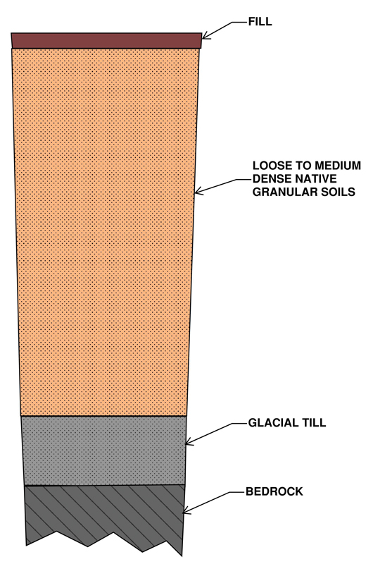
Nobis Group of Lowell, MA, completed a subsurface geotechnical investigation at the proposed building and parking lot site in 2017. The program consisted of ten borings, all terminating in glacial till or bedrock. The general subsurface profile consists of (top to bottom) a thin layer of granular fill, very loose to medium-dense native granular soils, medium dense to very-dense glacial till deposits, and bedrock (Figure 2). Groundwater was encountered from 1.8 to 3 feet below the ground surface. The granular soil layer includes a layer of saturated loose sands with minimal fines and Standard Penetration Test (SPT) blow counts (corrected to a hammer energy of 60%) as low as 4 blows per foot (bpf) and as high as 34 bpf.
Nobis Group completed an SPT-based liquefaction analysis using the Idriss and Boulanger procedure for each of the borings underneath the building. It determined that the soil profiles in four of the five borings underneath the building footprint include layers of soil susceptible to seismic-induced liquefaction ranging from 13 to 22 feet thick. Seismic-induced site settlement of up to 10 inches is predicted in the event of a maximum considered earthquake (MCE) (an earthquake with a 2,500-year return period). Nobis also identified that the liquefaction settlement would result in a significant down drag on the piles.
Site Class and Seismic Design Category
Minimum Design Loads for Buildings and Other Structures (ASCE/SEI 7-10), Section 20.3, requires that sites with liquefiable soils be classified as Site Class F and that a site response analysis be performed following Section 21.1 unless the structure has a fundamental period of vibration equal to or less than 0.5 seconds. The Commentary to ASCE/SEI 7-10 indicates that “ground motion data obtained in liquefied soil areas during earthquakes indicate that short-period ground motions are generally reduced in amplitude because of liquefaction, whereas long-period ground motions may be amplified by liquefaction.” After some strategic stiffening of the structure, SGH computed a period of 0.47 seconds for the building. Although a site response analysis was not required, the team still needed to assess and address liquefaction potential as a geologic hazard.
Site Class D would be applicable had liquefaction not been a concern. For this site class, the design seismic parameters are SMS equal to 0.371g, SM1 equal to 0.175g, SDS equal to 0.25g, and SD1 equal to 0.12g. The peak ground acceleration (PGAM) for the MCE is equal to 0.20g, which is used to determine the liquefaction potential. The seismic design parameters and the risk factor resulted in a seismic design category (SDC) of C.
Preliminary Design
The design team initially contemplated using ground improvement by installing rammed aggregate piers under the building footprint. This method would improve bearing capacities, reduce the risk of liquefaction by densifying the underlying soils with columns of compacted stone, and enable the use of shallow foundations and a conventional slab-on-grade. Ground improvement proved to be a feasible alternative to a deep foundation system. However, the projected cost savings were not significant, so the MBTA elected to pursue a more conventional driven pile solution to minimize disturbance to the underlying potentially contaminated soil and groundwater. The building site is elevated approximately 6 to 7 feet above the surrounding grade to provide resiliency against the projected 100-year flood. Therefore, all building-related pile cap and grade beam excavation would occur in uncontaminated fill.
Design for Foundation Stability
Ultimately, the foundation design included a conventional deep foundation system consisting of steel H-piles driven to glacial till or bedrock, reinforced concrete pile caps and grade beams, and a reinforced concrete two-way structural slab at grade. The selected foundation system mitigated the building’s susceptibility to settlement in an earthquake but did not address the liquefaction potential of the underlying soils. Liquefaction of the saturated clean sand layer can cause unbraced lengths of 22 to 26 feet. However, the HP14x73 piles have adequate strength to support applied axial loads for the unbraced lengths. Next, confirming that the foundation system could maintain lateral stability during an MCE-level earthquake was necessary as the soil profile moves horizontally in different amounts between the top and bottom of the unbraced lengths.
For the pile system’s lateral stability analysis, SGH conservatively assumed that the potential soil liquefaction would result in a 25-foot unbraced length for all piles. Next, the rotational fixity of the piles above and below the potential unbraced length was determined. The 2015 International Building Code (IBC), Article 1810.2.1, permits the assumption that piles are laterally supported 5 feet into stiff soil or 10 feet into soft soil. All piles are expected to develop full fixity at their base due to the requirement to drive piles a minimum of 5 feet into glacial till. However, full rotational fixity within a stiff soil layer is not assured above the potential unbraced length.
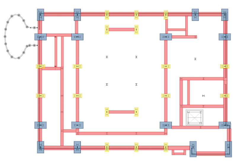
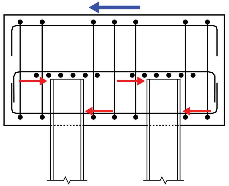
Therefore, eight piles near each corner of the building (32 piles total) are extended 20 inches into the pile cap to obtain rotational fixity at the top of these piles (Figure 3). Rotational fixity is obtained as a horizontal force couple develops between the top and bottom of the embedded portion of the pile (Figure 4). The approach is described in the U.S. Army Corps of Engineers, Report No. CERL TR M-339, Fixity of Members Embedded in Concrete. Although the general recommendation from this reference is to embed the pile two times the pile depth into the pile cap, the design team was able to reduce the embedment by specifically designing for the fixity. For pile caps providing pile fixity, reinforcement is specified near the bottom of the pile cap and a few inches above the top of the pile to spread the forces of the force couple. Grade beams prevent the pile caps from rotating. Where necessary to transfer the moment demand from the top of piles to the grade beams, the pile caps are designed for the torsion between the moments transferred from the piles and the rotational restraint provided by the grade beam. The analysis considered these 32 piles acting as a group to maintain the stability of all piles during liquefaction.
An estimate of the amount of differential movement between the top and bottom of the unbraced length of piles is required to determine the stability of the system. The movement can be estimated if the applicable spectral acceleration and period are known. Although the period of the pile system was not known, it could be conservatively assumed to be long. Using the transition period between the constant velocity and constant displacement portions of the design spectrum (TL) is sufficiently long because the expected displacement will be similar for longer periods. TL is equal to 6 seconds for the site, as obtained from Figure 22-12 of ASCE/SEI 7-10. The maximum spectral displacement for the MCE-level earthquake was computed using the known relationship between the spectral acceleration and spectral displacement for an undamped oscillating system.
- Spectral acceleration, Sa (at TL) = SM1 / TL
- Circular frequency, ω (at TL) = 2π / TL
- Spectral displacement, Sd (at TL) = Sa / ω2
For TL equal to 6s, SM1 equal to 0.175, and Sa equal to 0.029g, a spectral displacement of 10 inches results. Therefore, 10 inches was used as the maximum displacement with the seismic weight of the building and foundation structure to complete a P-delta analysis for the pile group. First, the shear demand on the group of fixed-fixed piles was computed and compared to the shear demand against the pile group’s shear capacity. SGH calculated the pile group’s shear capacity as the sum of the plastic moments at the top and bottom of the unbraced pile length accounting for the supported axial load divided by the unbraced pile length. Subsequently, the stability coefficient of the pile group was determined using ASCE/SEI 7-10 Equation 12.8-17. The resulting stability coefficient of 0.18 was less than Θmax. Therefore, the foundation system would remain stable in the event of seismic-induced liquefaction during an MCE-level earthquake.
Utilities
The potential for seismic-induced vertical settlement of 10 inches also had non-structural implications. For example, utility lines entering the building are ground-supported and could fracture near the interface with the pile-supported building if the predicted settlement occurred. Therefore, the design specified specialty flexible expansion joints at the building interface for critical utilities to accommodate this potential movement. While relatively common on the west coast, the use of this product was unique enough to require a variance from the Massachusetts Board of Registration of Plumbers and Gas Fitters.
Nearing Completion
Construction of the Iron Horse Park Operations Control Center is nearing successful completion. This essential critical facility is constructed on a site with geotechnical challenges that are unusual considerations for much of the United States. Accounting for the predicted seismic-induced displacements requires consideration of how they affect not only the building superstructure but also the foundation system and utilities. The practical approach taken to address the foundation design resulted in a building that will be ready to continue operations in a very rare earthquake.■
References
Castila, F., Martin, P., and Link, J. (1984). Fixity of Members Embedded in Concrete, US Army Corps of Engineers, Report No. CERL TR M-339.
American Society of Civil Engineers/Structural Engineering Institute (2010), Minimum Design Loads for Buildings and Other Structures (ASCE/SEI 7-10).