Boston University Center for Computing & Data Sciences
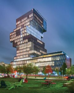
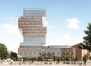
How do you build a 19-story, 305-foot-tall tower with 25-foot cantilever volumes offsetting in a counter-clockwise arrangement every two to three stories around the perimeter? Early discussions with Boston University, the design team of KPMB Architects, structural engineering firms Entuitive and LeMessurier, and construction manager Suffolk Construction identified the means and methods of erection as critical to the success of the Boston University’s Center for Computing & Data Sciences Building. Design-Assist, starting after the submission of Schematic Design, was utilized to identify the temporary erection procedures required to construct the tower. Steel fabricator, Canatal Industries, erector Prime Steel Erecting, and their engineer Simon Design Engineering were engaged to partner in the Design-Assist process with the design team.
In contrast to the traditional Design-Bid-Build, the Design-Assist delivery method engages the construction team to collaborate with the design team during the design development. The process encourages input from the construction team during the design phase. The goal of Design-Assist is to add value to the project by making informed decisions to identify constraints, improve constructability, reduce cost, and better define the construction schedule. A series of remote and in-person workshops were held on the Boston University project to facilitate the Design-Assist process. The team-building workshops allowed for discussion of critical information and constraints for parties, stress-testing concepts and details, and identifying action items and deliverables for discussion during subsequent meetings. These included methods for shoring and erection, the associated impact on the base-building structure, and cost and schedule impacts. Due to the constrained site, many shoring options were pursued to simplify construction and meet the project schedule, including impact on subsequent trades.
The ANSI/AISC 303, Code of Standard Practice for Steel Buildings and Bridges, notes, “The structural steel specifications shall include any special requirements for the fabrication and erection of the structural steel.” In addition, “The owner’s designated representative for design shall identify the following in the contract documents: a) The lateral-load-resisting system and connection diaphragm elements that provide for lateral strength and stability in the completed structure; and b) Any special erection conditions or other considerations that are required by the design concept, such as the use of shores, jacks or loads that must be adjusted as erection progresses to set or maintain camber, positions with specified tolerances or prestress.” Also, “Based upon the information provided”… “the erector shall determine, furnish and install all temporary supports, such as temporary guys, beams, falsework, cribbing or other elements required for the erection process.” For a more conventional building, the design and means and methods for erection have minimal impact on the base structure in the final condition. However, it was clear that given the structure’s complexity and three-dimensional nature, this process was not linear, and decisions by the construction team would impact the design of the base building structure and vice versa.
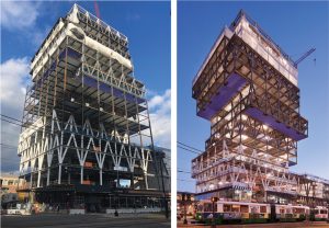
The primary structure consists of two-story-deep trusses made of wide flange steel and located along the perimeter of the building. Single-span trusses run the entire building length and are supported by a truss in the perpendicular direction at each end that cantilevers a single bay. Given the offset building massing and location of trusses, portions of the building are supported from below while other floors are hung from framing above. The concrete floor diaphragms attached to the concrete core provide lateral bracing of truss compression chords. This required all concrete floors at truss levels to be placed and reach strength prior to shoring removal. The steel framing and concrete floors were superelevated for 80 percent of the calculated dead load deflections. Steel columns and bracing was intumescent painted, AESS category 1, with exposed and polished concrete floors.
Per ANSI/AISC 303, the erector is responsible for “the means, methods, and safety of erection.” At the same time, the structural engineer of record is “responsible for the structural adequacy of design in the completed condition.” Temporary shoring by the steel erector is typically not designed for the weight of concrete. Shoring is commonly provided to a predetermined level to allow steel erection when the shoring is removed. Given the constraints of the structural system and the requirement to engage the concrete slab diaphragms for truss stability, temporary shoring was designed for steel erection, weight of concrete, and construction live loads.
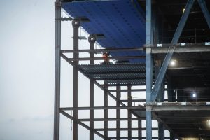
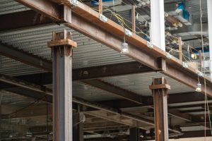
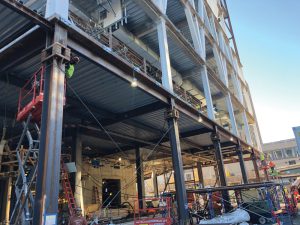
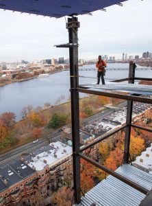
A total of 29 building columns do not extend to terra firma, requiring temporary support for construction. Full height shoring was provided to allow for erection of the steel and placement of concrete floors. Shoring consisted of wide flange columns extending between building cantilever volumes and extending to the structure below. Wide flange “beams” were provided between the temporary columns on alternating floors to brace the shoring back to the main building. These levels were decked with a 3-inch roof deck to serve as a working platform. Cable bracing was provided between shoring columns to provide stability for shoring columns in the other direction. The steel fabrication model included both the base-building steel for the building and temporary shoring and bracing. The temporary structure was designed for the anticipated dead-load of the structure and a 20-psf construction live load. Shoring column splices were coordinated to align with building column splicing to expedite the schedule and simplify steel erection. The complexity of the structure and the need to limit deflections to allow for curtainwall installation drove the team to consider multiple approaches and construction sequences.
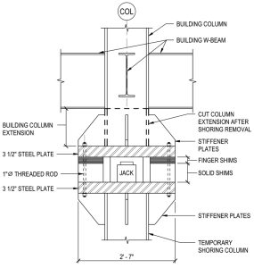
Jack boxes were designed into the top of shoring columns and bottom of building columns to allow for steel erection and shoring unloading. Careful consideration and detailing was required with a combination of cable stays and post-shore struts to ensure the stability of shoring columns at jack box locations during shoring unloading when the jack-box bolts were removed to allow for building movement. Stub column sections, part of the building columns at the top of jack boxes, were cut off after jacking.
Given the shoring scheme and sequence, the base building structure was designed for both the final and temporary conditions. Lower columns and hangers were designed for the additional axial loads resulting from upper temporary shoring. In addition, the lower framing and trusses were designed to act as a platform where lower shores could be removed prior to completing the upper trusses. This was done at the request of the contractor to allow for flexibility in construction sequencing. Superstructure elevations were carefully coordinated with the final determined erection, slab placement, and shoring removal sequencing.
The north and northeast corner of the tower cantilevers over the back ally adjacent to historic brownstone row housing, meaning there is no structure and foundation below to support the temporary shoring columns. Options evaluated in Design-Assist included temporary foundation elements, cantilever temporary shoring, or sloping temporary shoring columns to engage the mat-slab foundation. Temporary foundation elements consisting of multiple 100-ton H-piles with pile caps at each column were provided to simplify the shoring and erection. Deep foundation elements were required compared to shallow spread footings or cribbing, given the magnitude of the load and the requirement to limit differential settlement between the building supported by a mat slab 40 feet below grade and the temporary shoring columns. In addition, the large number of geothermal wells were installed before building construction. Careful coordination with geothermal well locations and the installation tolerance of the wells and H-piles was required to ensure that the wells were not damaged. Grade beams spanning up to 20 feet to pile-supported caps were required at some temporary shoring locations to minimize the risk of damaging geothermal wells.
Three tower columns located over the 5-story podium did not have associated building columns or sufficient building structure directly below to allow for support of shoring columns. Therefore, temporary dunnage framing consisting of W27 framing located at the lower level was provided to transfer loads to concrete foundation walls and the mat foundations.
Hydraulic jacks were used to gradually transfer load from the temporary shoring to the building framing and not impose dynamic loads on the base building structure. Given the three-dimensional nature of the structure and the desire not to add additional load to elements beyond their design load, all 27 tower columns would be unloaded at once. Depending on load, the load was transferred from the temporary shoring to the final building structure with 100 to 400-ton hydraulic jacks. This occurred simultaneously at 27 columns with 11 separate pumps, each manifolded to control multiple jacks. The jacking occurred at 4 floors due to the 3-D nature of the structure and location of shoring to building column transition. Loading was performed in 10% increments of the estimated self-weight of the supported structure. Calculated column unloading ranging from 100 to 700 kips depended on column location. Building elevations at each jack location were surveyed before and after jacking, with relative deflections at jack boxes monitored during unloading. Steel shims included in the jack box assembly were incrementally removed as the shoring was unloaded and the building deflected.
It was important with the Design Assist process to define clear roles and responsibilities regarding the design of temporary conditions during construction. The construction team was responsible for designing and documenting the temporary shoring and bracing and selecting jacks for unloading and detailing the associated jack boxes. In addition, at the request of Suffolk and approval of Boston University, the design team took on responsibility for the evaluation of temporary shoring loads (provided by the construction team) on the partially completed structure and design of temporary pile-supported foundations where shoring did not extend to terra firma.
The Design-Assist process included teamwork between the design and construction teams to make informed decisions on the building design beyond the temporary conditions during construction. The process allowed for early coordination with other trade partners, such as curtainwall, which also was engaged in Design-Assist. The process allowed for refinement of column splice details, beam connections, deck and connections to the concrete core, column splice locations, and evaluation of typical project details. Details were evaluated for cost and schedule with the design team, owner, detailer, fabricator, and erector as active participants.
The cantilevered structure of the building supported by the perimeter steel truss framing is an integral part of the architectural language. The structural steel framing is exposed to tell the story of the building. The Design-Assist process allowed an in-depth review of the architecturally exposed steel elements. Significant attention was afforded to the most prominently exposed connections. Representative truss connections were designed and detailed early in Design-Assist, with options presented as preliminary detailed shop drawings and “ifc” files for review. Connections were evaluated for cost, schedule impact, erectabilty, and visual appearance. Two full-scale mockups, one bolted and one welded, were constructed for review. The process allowed for the refinement of an all-field-bolted truss connection that was visually acceptable and supported the project budget and construction schedule. The Design-Assist process allowed for rigorous input to the design and appearance of the bolted connections. This included developing a set of hierarchical rules for the orientation of bolt heads, head types, etc., that were guided by which faces of the connections were most exposed to view. In the opposite sense, the process allowed influence from the architectural team to conceal steel truss connections in areas where their appearance was less desirable. Subtle moves were made to connections where connections were raised above ceilings or lowered to be concealed by the structural slab to fit with the building.
The Design-Assist process is a collaborative and team-focused approach to design and construction. The development of the structural steel design through Design-Assist for the Center for Computing & Data Sciences was a highly collaborative and occasionally social pursuit that helped build trust and confidence between the parties involved to benefit the project. The partnership was established very early in the design, and the team maintained an open dialogue throughout the design process. A consistent feedback loop that considered all aspects of the design, architecture, constructability, budget, and schedule was the foundation of the team’s approach. This collaboration and team-first mentality were the keys to making this project a success.■
See STRUCTURE’s January and June 2022 issues for additional articles on the Boston University Center for Computing & Data Sciences.
Project Team
Structural Engineer: LeMessurier
Structural Engineer: Entuitive
Architect: KPMB Architects
Construction Engineer: Simon Design Engineering
Contractor: Suffolk Construction
Steel Fabricator: Canatal Industries
Steel Erector: Prime Steel Erecting Inc.

