
Cast iron columns, commonly used in building construction in the 1800s and early 1900s, possess low tensile capacities and require special attention to detail in building alterations. 315 Hudson Street is a ten-story cast iron column building undergoing such alteration in New York City. Extensive renovations to the building included lowering a portion of the ground floor structure, transferring two off-grid columns at the ground floor via transfer beams at the second floor, and reinforcing columns for new rooftop loads. Each endeavor required novel detailing to brace, support, and reinforce the cast iron columns in a manner that limited tension on the cross-section.
315 Hudson Street was originally constructed in 1896 by the Henry Heide Candy Factory, maker of Jujyfruits® and Jujubes®. The building size was doubled with a horizontal addition in 1903 and doubled again with a second horizontal addition in 1911 (Figure 1). These original buildings framed a central yard infilled in 1962 with a new elevator core to create a unified office building after the candy factory relocated to New Brunswick, New Jersey. The 200- by 214-foot building includes 385,000 gross square feet. Jack Resnick and Sons, the owner of the commercial office space since the early 1960s, redeveloped the property into a Class A office building, with renovations completed in 2021 led by FX Collaborative Architects. The owner selected Gilsanz Murray Steficek to provide structural engineering services for this project based on the firm’s experience with historic building typologies and reputation for tackling unconventional problems.

Cast Iron Column Capacities
The buildings comprising 315 Hudson are composed of structural terracotta arch floors or draped mesh cinder concrete slabs, supported on steel or wrought iron beams that frame into cast iron columns. The perimeter walls and interior cores are multi-wythe brick. The floor live loads in the original construction varied from 150 to 300 psf.

Calculations governing the compressive capacity of cast iron columns have been present in the New York City Building Code (NYCBC) since at least 1899. However, these early capacities for cast iron compressive strength were deemed unconservative following a series of failures, and the code capacities were decreased in 1916. A comparison of the allowable stresses before and after 1916 is shown in Figure 2. As allowable stress values decreased, many older buildings found it challenging to justify renovations and alterations that increased the load on individual columns. In renovations, cast iron columns are often replaced or supplemented by new steel columns positioned on two or more sides so as not to create unbalanced loading in the cast iron. In the case of 315 Hudson, the building’s original factory live loads were reduced to live loads between 50 psf and 150 psf based on the new occupancies, and the capacity of the columns was re-evaluated under the 1916 code. The 1916 formulas are referenced in the 1938 and 1968 NYCBCs, which are utilized for existing buildings today.
The 1916 NYCBC also specifies the allowable short-column compressive capacity (16,000 psi), shear capacity (3,000 psi), and tensile capacity (3,000 psi) of cast iron. The bending capacity is similarly 16,000 psi on the compression side and 3,000 psi on the tension side. These values are utilized in checking local stresses at areas such as beam connections and bearing plates using an elastic analysis. Cast iron is not utilized under gross tension as it behaves brittlely, and there is no yield plateau.
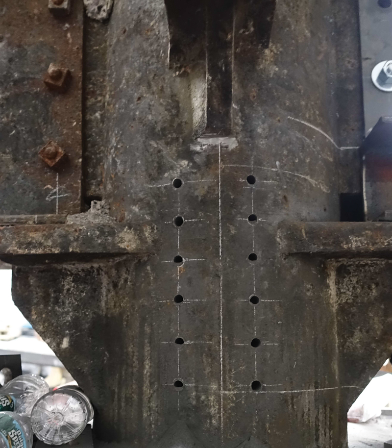
Welding to cast iron is difficult due to its high carbon content, which can lead to brittleness and cracking of the weld material. As such, all connections to existing cast iron were made via drilled and tapped bolts (Figure 3). The tapped holes and bolts were typically ¾ inch in diameter or smaller and extended into the cast iron column for its full thickness. The tap and drill diameters were selected to achieve a minimum of 75% thread engagement. Where columns are round, the connection plates are curved to match the diameter of the column. The bolts to cast iron were specified as A307 grade, not high strength because A307 is more ductile, and the bearing on the cast iron column controls at the bolt interface. The Structural Engineering Association of New York (SEAoNY) has also put together resources on cast iron columns, reporting engineers satisfactorily using holes up to 1-inch-diameter at 4-inch spacing.
The drawings for the 1896, 1903, and 1911 building construction are lost to time. As such, extensive probes were conducted throughout the building to verify column diameters, column wall thicknesses, column seat dimensions, framing sizes, and slab reinforcing. Due to the fire encasement on the columns, only half of the column was exposed. Therefore, a tree caliper was used to verify the column diameter. Holes were drilled on each side of the column, and the average column thickness was determined. Per the 1916 building code, wherever the core of a cast iron column has shifted more than one-fourth of the thickness of the shell, the thickness of the metal all around is assumed equal to the thinnest part.
Lowering the Ground Floor
The sidewalk elevation around the building varies by approximately two feet. The building elevations of the horizontal additions generally match the original 1896 building floor elevations. This created a situation where much of the ground floor was elevated above the existing sidewalk and not ADA-compliant. Over time, the ground floor was subdivided into several retail spaces with different points of entry, and customers had to step up from the sidewalk into these spaces. From an accessibility and a marketing perspective, this is undesirable. The owner elected to lower the ground floor of the bulk of the 1903 horizontal addition to be level with the sidewalk on Hudson Street, creating a retail space and a lobby accessible from the sidewalk without the use of ramps. Probes revealed that finishes on the ground floor slab were layered on top of each other for over a century (Figure 4). This heavy build-up was removed to gain depth. However, it was still necessary to lower the structural slab and associated framing by approximately nine inches in the retail bays and 21 inches in the lobby bays.

Each cast iron column in this retail space supports the eight floors and a roof above and carries between 500 and 700 kips. Removing and lowering the floor slab required temporary bracing of the cast iron columns to provide stability until the new floor was in place. The initial scheme to support the cast iron consisted of direct bracing utilizing steel beams. As this option was explored further, hand calculations and finite element analysis of the column cross-section revealed that point bracing, with a pair of compressive or tensile loads on opposite faces of the columns, induced bending within the circular column cross-section that exceeded the allowable tensile stress.

The area of the lowered ground floor consists of twelve interior columns and twenty-one bays of framing. To laterally support the columns uniformly, similar to the support provided by the slab in the existing condition, the steel bracing members terminated in steel collars filled with grout encasing the column (Figure 5). Where the collar was offset from the brace, the tubular steel bracing members were designed to carry the axial bracing force and the resulting eccentricity. Braces were positioned below the slab, allowing unimpeded access to frame the new floor above (Figure 6). The braces were gravity supported to the foundations below. They sloped up at the perimeters of the opening to bear against the structural slab in the adjacent areas of the building. Nodal bracing forces considered cumulative loads from the possibility of multiple columns in a row buckling simultaneously.

The existing slab was demolished to make way for the new lowered floor. The pairs of existing 21-inch girders were removed and replaced with pairs of new composite W14s. The new girders were coped to bear or hang from the existing seats. The existing 10-inch infill beams were removed and replaced with a new composite slab with 12-foot spans (Figure 7).

Transferring Columns at the Second Floor
The renovation of the building included an enlarged three-bay-wide lobby on Hudson Street that extends back to the elevator core in the center of the building. Unfortunately, two lobby columns were off-grid and did not work aesthetically with the conceptual designs. These off-grid columns were located within the former front façade and rear courtyard walls.
A pair of wide flange columns matching the desired gridlines was added at each column transfer location to remove these two off-grid columns at the ground floor. A transfer girder composed of a pair of 28-inch-deep by 6-inch-wide built-up channel members was designed to be bolted to the outside face of each flange of the new columns and pick up the cast iron column above. A bolster was fabricated to support the flanges of the cast iron above and taper down to the wider spacing of the transfer girders below. The contractor substituted 4-inch solid plates in place of welding the built-up channels.

The load was jacked from the existing second-floor column into the new steel through a permanent steel collar with up to 144 drilled and tapped bolts (Figure 8). This collar is connected to temporary jacking beams on either side of the existing column. A pair of jacks were used to transfer the existing load on the column into the new transfer beams and pre-deflect them before removing the cast iron column below (Figure 9). After the load transfer, the existing first-floor cast iron columns were removed with exothermic cutting rods.

The new columns were transferred back to the existing foundation at the unoccupied subcellar level to avoid new foundations and potential settlement. This transfer was accomplished with a concrete grade beam supported on the existing footing and an outrigger to the adjacent column foundation for stability.
Reinforcing Cast Iron Columns
New mechanical systems for the building, as well as a green roof, rooftop assembly space, and roof terrace, imposed additional loads at the building’s upper levels. This led to the overstress of some columns at the top of the building when checking their capacity by the 1916 formula. Due to the high live load capacities of the original floors, and the lower live loads from the new occupancies, this overstress quickly dissipated, and the columns on the lower floors did not need to be reinforced.

The method of reinforcing consisted of steel half pipe shells with welded shear studs on the inside (Figure 10). The cast iron column was drilled and tapped with a series of A307 bolts. The half pipe shells with shear studs were joined to the cast iron column by structural grout poured into the interface. This grout bore on the cap plate of the larger column on the floor below. The reinforcing was checked in multiple ways: to provide load transfer between the shear studs and tapped bolts using the grout interface, using the added shell to brace the inner column, and passing loads through the shell/grout through bearing on the columns below. Where reinforcing was required at more than one upper floor, four steel angles were threaded between the existing beams to carry the load from one reinforcing shell to another.
Another cause for reinforcing at the uppermost level was unbalanced loading. When the new mechanical equipment or roof deck resulted in a larger shear reaction on one side of the column than the other, this induced an eccentricity into the column. When this moment or the local shear and tensile stresses at the connection resulted in tension of more than 3 ksi in the column or seat, column and connection reinforcing were implemented, or strategies were undertaken to reduce the eccentricity on the column through modifying the framing connections. Overstressed existing connections were reinforced by new tee supports under the existing seats, which were welded to the reinforcing shells.
Where new steel columns for the rooftop assembly area, a courtyard infill, and mechanical equipment dunnages were installed on top of the existing cast iron columns, care was taken not to transfer moment from the new steel into the existing cast iron. The cast iron cap plates with their four holes were used to connect the new steel columns, but the new steel columns were coped at the base to limit the amount of moment which could be transferred and to make the connection behave more like a pin.
Historic cast iron column buildings require special attention during renovations. Care to detail, research into prior editions of building codes, experience, and knowledge-sharing among engineers can help some of these buildings survive and adapt for another century.■
Project Team
Owner and Manager: Jack Resnick and Sons
Structural Engineer: Gilsanz Murray Steficek LLP Engineers and Architects
Mechanical, Electrical, Plumbing Engineer: Dagher Engineering PLLC
General Contractor – Ground Floor Retail: ZDG Construction Management
Architect – Ground Floor Retail: Specter DeSouza Architects
Steel Fabricator/Erector – Ground Floor Retail, Rooftop Mechanical: Maspeth Welding Inc.
Architect – Lobby, Rooftop, Redevelopment: FX Collaborative Architects LLP
Steel Fabricator/Erector – Lobby, Rooftop, Redevelopment: Koenig Iron Works Inc.
General Contractor – Rooftop, Redevelopment: Structure Tone
General Contractor – Lobby, Rooftop Mechanical: JRM – Construction Management LLC
Steel Fabricator/Erector – Rooftop Mechanical: FJM- Ferro