
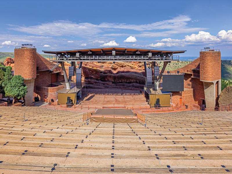
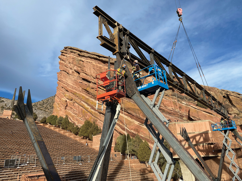
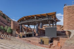
Red Rocks Amphitheater is considered one of the world’s premier concert venues. Located in Morrison, Colorado, the open-air concept was constructed between a series of sandstone rock formations, creating a natural amphitheater with some of the best acoustics and visuals in the world. When the amphitheater first opened in 1941, the stage was uncovered and exposed to rain and snow, which could arrive at a moment’s notice traveling over Colorado’s Rocky Mountain Front Range. The stage remained uncovered until 1989, when a steel space frame was constructed out of small diameter pipe sections. For 30 years, the original stage roof was functional to shelter performers from the elements. Still, over time, the roof was deemed structurally insufficient due to rigging issues inherent to its design and increased rigging demands as shows became larger from a production standpoint. Therefore, the facility owner and the City and County of Denver asked for the complete removal of the existing roof structure and a replacement structure with an increased rigging capacity, which was safer to use and complemented the surrounding setting.
The 1989 roof structure had a rigging capacity of 38,000 pounds – insufficient for the requirements of modern concerts. The original roof framing required temporary concert point loads (lights and speakers) to be rigged using cables hung diagonally from stationary roof members, known as bridling. Bridling can be laborious and dangerous for workers as they orchestrate precise supporting point loads tied off to lifelines while climbing the roof framing.
These factors drove the owner to set new performance criteria, including a minimum rigging capacity of 150,000 pounds and a walking surface with perimeter guard railing to allow workers to safely work within the new roof without fall protection restraints. The new roof structure included an additional 2,500 square feet of coverage to protect as much of the stage floor as possible compared to the old roof’s footprint.
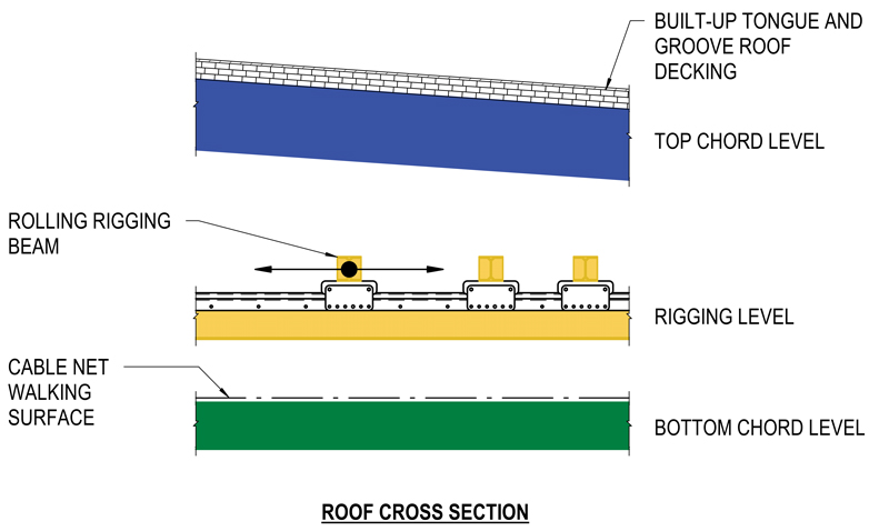
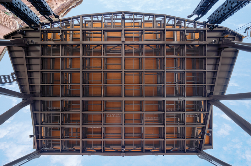
For the new construction, primary and secondary (bridging) roof trusses comprise the main gravity load-resisting system supporting a series of infill steel members. The new roof structure can be divided into three distinct layers (from top to bottom): top chord framing, rigging level, and bottom chord framing (Figure 1).
At the top chord level, at the architecture team’s request, linseed oil finished tongue and groove decking spans approximately ten feet between the top chord steel beams and trusses. The decking acts structurally to resist wind, seismic, and snow loading while doubling as the exposed finished surface, further complementing the natural surrounding red rocks. Because tongue and groove decking does not provide high diaphragm shear capacity, a layer of structural sheathing was introduced above the tongue and groove decking, which spans to the lateral load resisting moment frames in each direction.
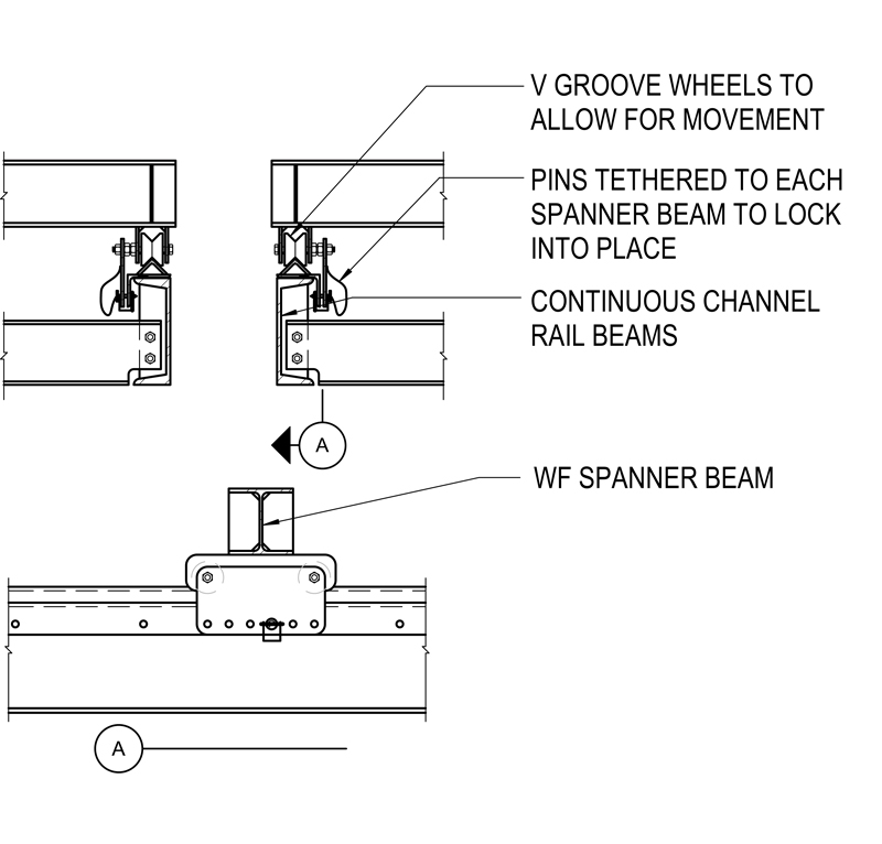
Moving down to the rigging level, the most critical design innovation incorporated into the new stage roof is its fluidity of rigging configurations. These configurations were made possible by a series of waist-high rail-supported rolling rigging beams (approximately 2.5 feet above the walking surface), which can be positioned directly above temporary concert point loads to eliminate bridling. With each beam supported on two wheels at each end, riggers can easily move these beams to locate precisely where each show requires items to be hung below. Once these members are located, pins tethered to each beam lock the structure into place to ensure no further movement occurs (Figure 2).
At the bottom chord level, riggers maneuver through the roof space on a woven aircraft cable tension grid walking surface to position the waist-high rolling beams anywhere over the stage floor. This cable grid allows rigging suspensions to pass from the rolling beams, through the walking surface, to the rigged point below the roof trusses. This combined system of the tension grid and rolling beams eliminates any unsafe bridling or the need for fall protection.
These features reduce the owner’s ongoing operating expenses (realized through reduced labor to rig each show) and open this world-class venue to performances previously excluded due to limited rigging capacity.
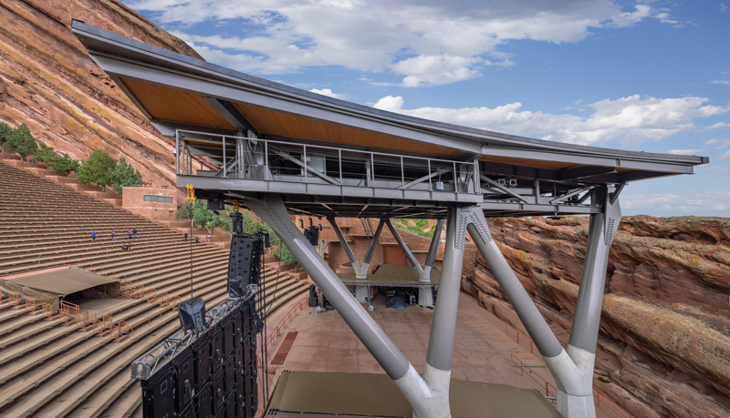
In addition to an increased rigging demand, the City and County of Denver desired better sightlines to the performers on stage from the seating bowl. The original stage roof utilized twelve columns to support the roof structure, and some patron views were obstructed in certain areas of the seating bowl. The column quantity was reduced from twelve to four, and the columns were held back from the front of the stage to open the new configuration’s field of view to benefit both the performers and the audience. These column locations created a large roof cantilever to ensure it was still covering the performers below at the front of the stage. Once the new columns extend fourteen feet above the stage floor, the four vertical columns transition to a series of “W” columns to help stiffen the cantilevered roof edge. This “W” shaped column configuration was closely coordinated with the architect and the City and County of Denver to ensure the architecture complemented the natural surroundings.
Green room spaces below the stage floor also created challenges in locating the four new columns. The existing stage floor structure is a cast-in-place one-way slab and beam system supported by concrete columns or shear walls. Since these spaces below the stage floor were not reconfigured, column locations were carefully selected to avoid existing concrete beams, shear walls, and columns. This resulted in an asymmetrical configuration but still allowed for pedestrian flow without eliminating any established green rooms.
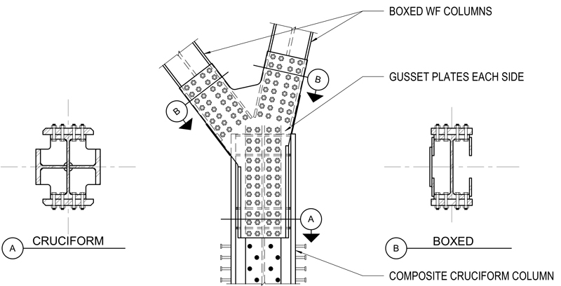
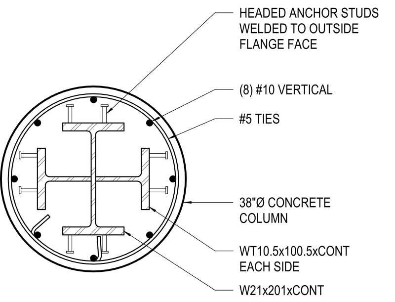
The new roof structure utilizes moment frames in each direction to maximize open space at the stage floor, with the primary and secondary roof trusses participating in the lateral system for both strength and stiffness. To resist ultimate wind speeds of 170 mph in this special wind region, and because column bending demand increases moving down from the roof structure, the steel column shapes transition from a boxed wide flange shape at the “W” columns to a cruciform steel shape with composite structural concrete wraps at the vertical portion of the columns. Headed studs tie the cruciform steel shape to the concrete causing the two materials to act compositely, gaining strength and stiffness where the bending moments are the largest (Figures 3, 4, and 5).
Founding the new columns presented a construction challenge as compressive and sustained tension column loads forced the use of micropiles and pile caps, both of which needed to be installed within the low ceiling height below the stage. The columns were tucked into corners of the existing construction to avoid impeding the existing architectural layout. This resulted in pile caps ranging from 36 inches at concentrically loaded pile groups to 60 inches thick at eccentrically loaded pile groups to accommodate existing construction. 34 micropiles, with 90 kips axial service compressive capacity each, were installed to resist the new column loading.
The $6 million stage roof replacement serves the City and County of Denver’s needs to accommodate modern rigging demands while providing a safe space for workers to rig the many shows the world-famous venue holds. In addition, with unobstructed sightlines, concertgoers can now view any of the performers from any location throughout this iconic venue.■
Project Team
Owner: City and County of Denver
Structural Engineer-of-Record: Martin/Martin, Inc., Lakewood, CO
Architect of Record: Short Elliot Hendrickson, Inc., Denver, CO
General Contractor: GH Phipps