
The design of structures utilized to support fall protection systems (FPS) for workers at height is a topic that is often researched and questioned but is not a straightforward process. Unlike other common structures with design requirements such as loads, factors of safety, and minimum requirements defined in their respective codes and design guides, the design requirements for fall protection loads can be somewhat ambiguous. This article aims to provide a basic overview of FPS, define what regulations and standards exist in this space, and recommend a best practice approach for engineers to define strength requirements for fall protection anchorages.
Why is fall protection so important? A United States Bureau of Labor Statistics news release dated December 16, 2021, states that in the U.S. alone, a worker died every 111 minutes in 2020 from a work-related injury. Of the 4,764 occupational fatalities in that year, 645 resulted from a worker falling from a height to a lower level. Falls to a lower level were the second leading occupational fatality across all industries following transportation incidents. Additionally, falls were the leading cause of workplace fatalities in the construction industry.
ABCs and the Science of a Fall
What components comprise a personal FPS? United States Occupational Health and Safety Administration (OSHA) defines a personal FPS in OSHA 1910.140 as: “Personal fall protection system means a system (including all components) an employer uses to provide protection from falling or to safely arrest an employee’s fall if one occurs.”
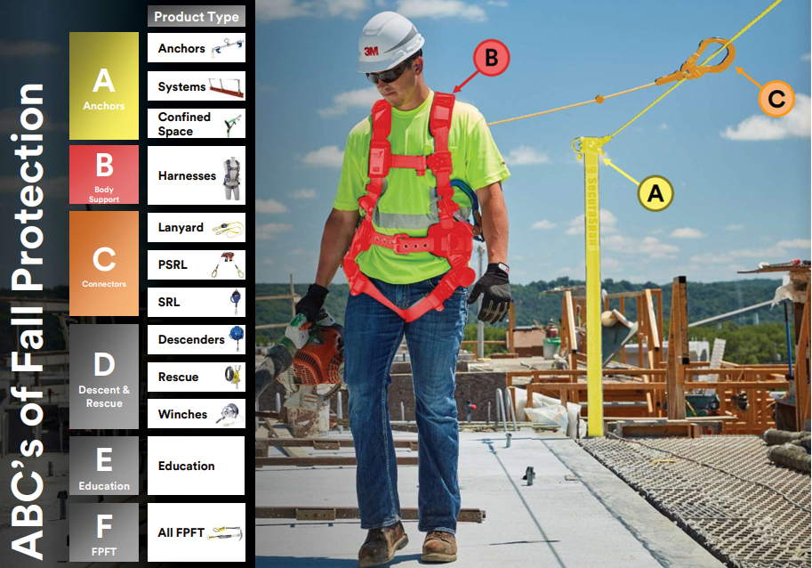
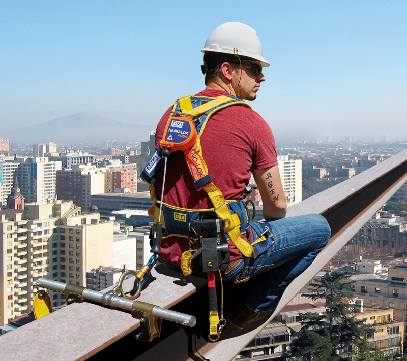
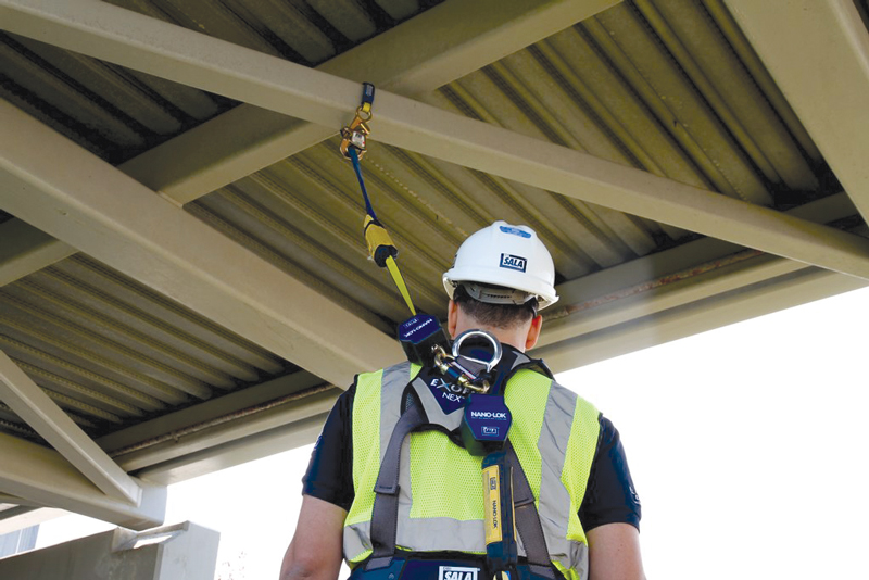
Elementary ABCs are utilized in the fall protection industry to lay out the basic components of fall protection. Figure 1 shows the primary components of an FPS. Also, note the additional components one should always consider. In the graphic:
- A stands for anchorage. Anchorages are a secure attachment point for an FPS, varying by industry, job, type of installation, and structure.
- B stands for body support. Body support in a personal FPS is typically a full body harness that distributes fall forces over the upper thighs, pelvis, chest, and shoulders.
- C stands for connector. Connectors in a personal FPS are typically self-retracting lifelines (SRL), shock-absorbing lanyards, or restraint lanyards.
- D stands for descent and rescue. Descent and rescue devices raise or lower a fallen and/or injured worker to safety or rescue/retrieve them from a confined space.
- E stands for education. Education is essential in specifying and using a personal FPS. The specifier, as well as the user, must be properly trained in fall protection.
- F stands for fall protection for tools. Fall protection for tools and dropped object prevention help make work environments safer and more productive by helping reduce dropped object incidents.
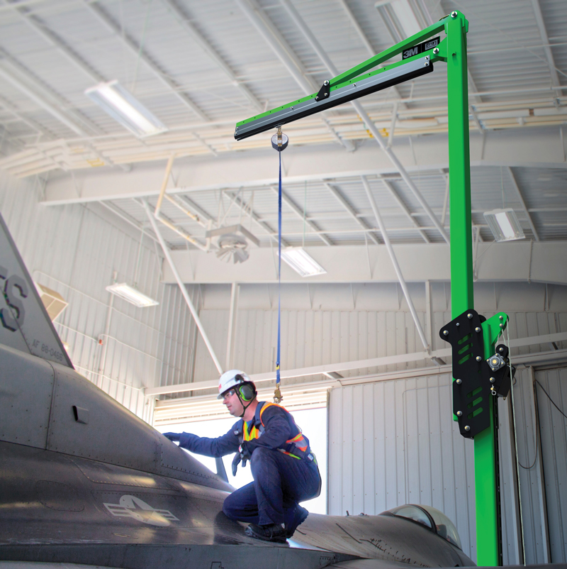
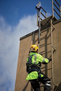
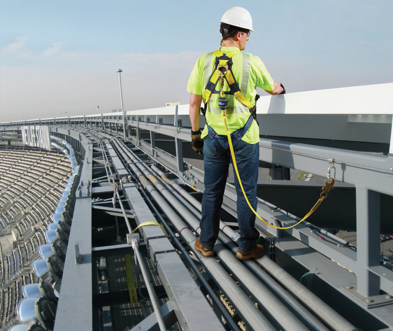
All of these components work together to form a complete personal FPS. Figures 2 through 6 provide examples of FPS combinations and applications.
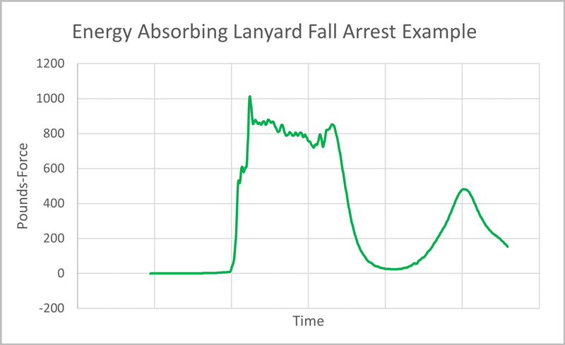
The science of a fall and the forces transferred to the anchorage point create a unique design load scenario. When a worker falls, a force is generated that can vary depending on their weight, position, fall distance, PPE, and various other factors. This is referred to as their fall arrest force in the fall protection industry.
The human body is likely to sustain a range of mild to life-threatening injuries if subjected to this entire fall arrest force, particularly if the harness is not worn correctly. This is why fall protection products are required and designed to absorb and limit the fall arrest force. Fall protection products are designed to reduce these forces using energy absorbers such as a tearaway web or a rotating friction brake. These energy absorbers limit the fall arrest forces transferred through the FPS and safely arrest the worker’s fall. Figure 7 shows an example of a tear web energy absorber, and Figure 8 shows an example of a rotating friction brake. Both are examples of the force vs. time distribution in a fall event using an energy-absorbing lanyard or self-retracting lifeline as a connector in an FPS.

Standards and Regulations
Some specific standards and regulations apply to an FPS based on where the personal protective equipment (PPE) is used worldwide. Regulations vary by country and, in some cases, by state. Most FPS are regulated by the respective country’s government occupational health and safety authority. In the United States, this is OSHA. In addition to the requirements set forth by the regulatory body, standard-setting organizations have detailed design and testing criteria that manufacturers can use to receive a certification mark. In the U.S., for example, the American National Standards Institute (ANSI) maintains a set of standards for the design and testing of FPS, ANSI/ASSP Z359 Fall Protection Standards. The remainder of this article focuses on U.S. practice.
At a minimum, an employer must use an OSHA-compliant FPS. In addition, some state-level OSHA regulations maintain that all FPS must be ANSI/ASSP Z359 compliant. Therefore, as a best practice, employers and engineers are recommended to purchase, specify, and design FPS that are OSHA and ANSI/ASSP Z359 compliant unless under a specific circumstance.
Regarding FPS anchorages, it is important to understand the OSHA definitions of competent and qualified persons. OSHA 1910.140: “Competent person means a person who is capable of identifying existing and predictable hazards in any personal fall protection system or any component of it, as well as in their application and uses with related equipment, and who has authorization to take prompt, corrective action to eliminate the identified hazards,” whereas “Qualified describes a person who, by possession of a recognized degree, certificate, or professional standing, or who by extensive knowledge, training, and experience has successfully demonstrated the ability to solve or resolve problems relating to the subject matter, the work, or the project” (emphasis added).
Typically, a safety professional who is educated on FPS and able to specify equipment is a competent person. A qualified person is usually an engineer who is educated on FPS, able to calculate structural loads, and able to qualify that the anchorage point can adequately support the FPS. In many cases, the employer/owner responsible for the FPS may require this engineer to be a professional engineer.
Anchorage design strength requirements are determined based on whether a competent or qualified person evaluates the anchorage strength. OSHA breaks these two anchorage designations into non-certified and certified anchorages. A non-certified anchorage, according to OSHA 1910.140(c)(13)(i), is defined as “capable of supporting at least 5,000 pounds (22.2 kN) for each employee attached.” A certified anchorage, according to OSHA 1910.140(c)(13)(ii), is defined as “designed, installed, and used, under the supervision of a qualified person, as part of a complete personal fall protection system that maintains a safety factor of at least two.” ANSI/ASSP Z359.0 defines these two anchorage strength requirements in section 2.110: Non-Certified Fall Arrest Anchorage, “A fall arrest anchorage that a competent person can judge to be capable of supporting the predetermined anchorage forces as prescribed in these standards.” Section 2.23 defines certified anchorage as “an anchorage for fall arrest, positioning, restraint or rescue systems that a qualified person certifies to be capable of supporting the potential fall forces that could be encountered during a fall or that meet the criteria for a certified anchorage prescribed in these standards.” (Emphasis added.)
What does this mean for anchorage design? A non-certified anchorage must be capable of supporting 5,000 pounds and requires a competent person to sign off on it. At the competent-person level, general guidance is, can you hang a half-ton pickup truck off the anchor point? A certified anchorage requires a qualified person to design and/or sign off on the anchorage. A factor of safety (FOS) of 2:1 means the anchor can hold twice the foreseeable load.
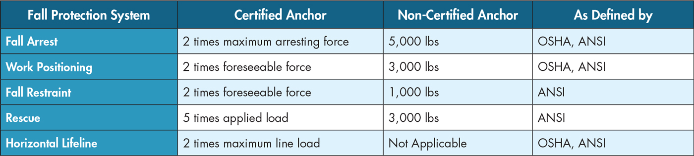
An FPS can be used for fall arrest, work positioning, fall restraint, rescue, and horizontal lifelines, each requiring different anchorage strength. The Table provides an overview of different anchorage strength requirements. 3M also provides a technical bulletin detailing these requirements – https://bit.ly/3QymlBU.
Hierarchy of Anchorage Design
How should engineers approach the design of an anchorage point as a qualified person? A typical approach is to start with the highest anchorage strength achievable and then sharpen the pencil as needed to deem an anchor point as adequate. As anchorage design strength is reduced, additional controls are needed to ensure the design strength is never met or exceeded. This anchorage design approach is called the hierarchy of anchorage design strength for qualified persons.
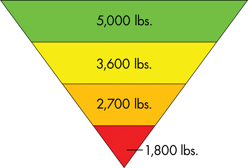
As shown in Figure 9, the starting point is 5,000 pounds (22.2 kN). This anchorage strength can be selected by a competent person or designed by a qualified person. This can either be a non-certified anchorage or a certified anchorage. A qualified person should always begin with this load to evaluate if the anchorage can meet that conservative requirement.
The next step is 3,600 pounds (16 kN) which makes this anchorage no longer a non-certified anchorage. It is now a certified anchorage that a qualified person selects. This load includes an FOS of 2:1, which means it is designed to hold 1,800 pounds (8 kN). OSHA 1910.140(d)(1)(i) states that the employer must “limit the maximum arresting force on the employee to 1,800 pounds.” Due to this federal regulation, all FPS components in the U.S. must limit the arrest forces in an FPS to 1,800 pounds. Manufacturers of fall protection products utilize energy absorption methods to reduce fall arrest forces and meet OSHA requirements. This means that regardless of which manufacturer’s fall protection products one uses, the anchorage point is not subjected to a load greater than 1,800 pounds so long as the FPS is OSHA compliant and is used following the manufacturer’s user instructions. Therefore, this 3,600-pound load is considered the industry standard design load for a certified anchorage.
The next step is 2,700 pounds (12 kN). This load can only be used for a certified anchorage designed by a qualified person. This 2,700- pounds anchorage load includes an FOS of 2:1, meaning it is designed to hold 1,350 pounds (6 kN). Manufacturers may design and sell products with a maximum arrest force of less than 1,800 pounds (8 kN) to provide additional user value and comply with specific standards such as ANSI/ASSP Z359. The ANSI/ASSP Z359 set of standards establishes the maximum arrest force in some product classes for a personal FPS to be 1,350 pounds. Therefore, if an engineer needs to design the anchorage strength down to 2,700 pounds, they can do this by specifying that only FPS components with a maximum arrest force of 1,350 pounds may be utilized with this anchorage point. When designing to this anchorage strength load, it is highly recommended to put controls in place to either make the specific FPS components unable to be switched with components not complying with the 1,350 pounds maximum arrest force requirement or “lock-out/tag-out” (LOTO) the system to require a check to be performed to confirm all components are compliant before utilizing the FPS.
The last level is 1,800 pounds. This load can only be used for a certified anchorage designed by a qualified person. The FOS of 2:1 means this 1,800-pound anchorage load is designed to hold 900 pounds (4 kN). As discussed previously, manufacturers can choose to design and sell products with less than the OSHA’s 1,800 pounds maximum arrest force; some manufacturers do sell FPS components with a 900 pounds maximum arrest force for applications such as this. Engineers needing to design the anchorage down for this load must specify that only FPS components with a maximum arrest force of 900 pounds may be utilized with the anchorage point. It is highly recommended to put controls in place to either make the complete FPS components unable to be switched with components not complying with the 900 pounds maximum arrest force requirement or use the LOTO approach, as previously mentioned. A qualified person should only choose to design this load with great caution and appropriate controls in place. This design load level should only be considered if all other options are unattainable, and the fall protection hazard cannot be avoided altogether.
Structural Design Considerations
When an engineer designs an FPS fall arrest anchorage, what considerations should be taken? Fall protection anchorage loads fall into a unique category where requirements are specified by OSHA and do not fall under any specific sections of typical engineers’ building or material design codes. However, there are two key points to consider when designing fall arrest anchorages.
First, the anchorage structure is allowed to deform in a fall arrest event. It is the responsibility of the engineer to determine acceptable deformation limits. If deformation is allowed in the anchorage design, testing a sacrificial anchorage point is recommended to confirm that the structure performs as designed. If an anchorage point is subjected to a fall event, the anchorage point and FPS components must all be taken out of service and discarded or repaired.
Second, consider safety factors. As noted previously, OSHA requires a 2:1 FOS for all FPS, including the anchorage structure. When pre-engineered fall protection products are intended to be attached to an anchorage structure, the manufacturer typically specifies an anchorage strength requirement. These anchorage strength requirement values typically already include a 2:1 FOS. Always confirm with the manufacturer if you are unsure if the FOS load is included. Due to fall-protection anchorage loads falling into the OSHA category rather than a traditional structure’s design code or material code, this OSHA 2:1 FOS is usually the only required safety or load factor for the design of an FPS anchorage. It is at the discretion of the engineer, employer, structure owner, and local authorities if an additional load factor is required. An engineer needs to have a respectable education in FPS before being deemed a qualified person to design FPS anchorage structures.
Conclusion
The design of an FPS anchorage can be quite simple from a requirement and design complexity standpoint but should also be undertaken with great discernment for the purposes it is used for in the event of a fall. Always check for specific local or structure-owner design requirements and the specific manufacturer’s instructions for the FPS components being utilized. The hierarchy of anchorage design strength approach is a best practice to begin conservatively and reduce if needed while taking great consideration when doing so. From a worker’s safety approach, when specifying/designing an FPS/anchorage, always stop and first reconsider if there is a way to design out the need for that employee to be working at heights in the first place.■
Reference
BLS. (2021). National Census of Fatal Occupational Injuries in 2020. U.S. Department of Labor.