
Per ACI 318-19 and ASCE 7-22
This article provides background on the recognition of ductile coupled shear wall systems of reinforced concrete in ASCE 7-22 Minimum Design Loads and Associated Criteria for Buildings and Other Structures (ASCE 2022) Table 12.2-1, Design Coefficients and Factors for Seismic Force-Resisting Systems. The system itself is defined in ACI 318-19 Building Code Requirements for Structural Concrete (ACI 2019).
Reinforced concrete shear walls are commonly used in buildings for functional as well as structural reasons. Functionally, shear walls are useful in buildings because they serve as partitions between spaces. Structurally, they make buildings laterally stiff, particularly when used interactively with moment frames, thereby helping to keep lateral deflections within desirable or tolerable limits.
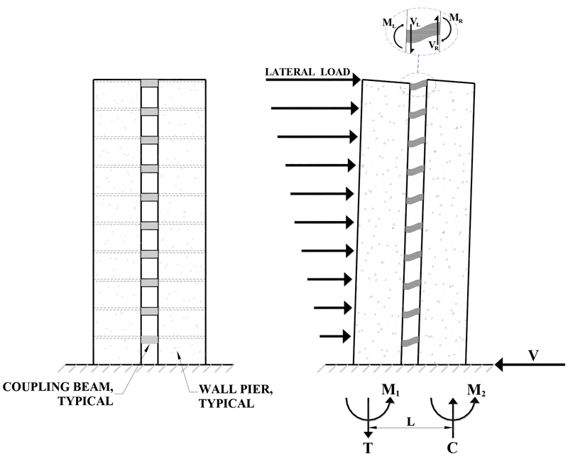
Often, such walls are pierced by numerous openings for windows, doors, and other purposes. Two or more walls separated by vertical rows of openings, with beams at every floor level between the vertically arranged openings, are referred to as coupled shear walls. When a coupled shear wall system is subject to lateral wind loads or earthquake forces, shear forces are generated at the ends of the coupling beams. These accumulate into a tensile force in one of the vertical wall segments and a compressive force in the other vertical wall segment. Due to these tensile and compressive forces, the couple resists a part of the overturning moment at the base of the wall system, leaving the remainder of the overturning moment to be resisted by the vertical wall segments themselves (Figure 1).
The ratio of the overturning moment resisted by the tension-compression couple to the total overturning moment at the base of the coupled wall system is often referred to as the degree of coupling. The shorter and deeper the coupling beams, the higher the degree of coupling. When the degree of coupling is very low, the two vertical wall segments tend to behave like individual isolated walls. When the degree of coupling is very high, the entire coupled wall system tends to behave like a shear wall with openings. However, it should be noted that as inelastic displacements develop in the coupling beams, the degree of coupling tends to lose its significance.
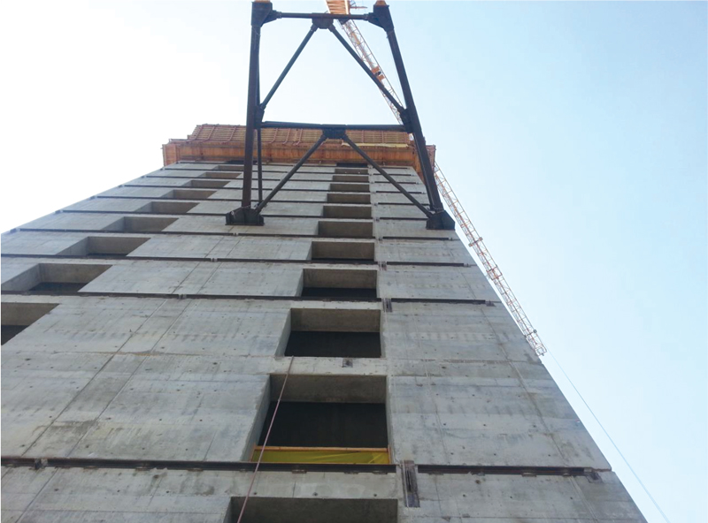
An example of a coupled shear wall system is shown in Figure 2. The vertical wall segments are often referred to as wall piers. This article avoids this terminology because “wall pier” is a defined term in ACI 318. Many vertical wall segments forming part of a coupled shear wall do not satisfy the ACI 318 definition of wall pier.
A coupled shear wall system can be designed to dissipate a considerable amount of earthquake energy in the coupling beams before flexural hinges form in the walls. This typically occurs at the bases of slender vertical wall segments with height-to-length ratios larger than or equal to two. Energy dissipation in coupling beams can be by shear yielding if their span-to-depth ratios are low. Flexural yielding at the ends of coupling beams occurs if their span-to-depth ratios are larger.
Although such coupled wall systems are highly suitable as the seismic force-resisting systems of multistory buildings, they were not recognized as distinct entities in Table 12.2-1 of ASCE 7 through its 2016 edition. Therefore, such systems needed to be designed using R-values that essentially ignored the considerable benefits of having the coupling beams, which can dissipate much of the energy generated by earthquake excitation. This article reports on a successful effort to remedy this situation.
Coupled shear wall systems are recognized as distinct from isolated shear wall systems in Canadian (CSA Group 2014) and New Zealand (Standards New Zealand 2006) standards. They are also accorded higher response modification factors, given their superior seismic performance.
ACI 318-19 Provisions
According to Bertero (1977): “Use of coupled walls in seismic-resistant design seems to have great potential. To realize this potential, it would be necessary to prove that it is possible to design and construct ‘ductile coupling girders’ and ‘ductile walls’ that can supply the required strength, stiffness, and stability and dissipate significant amounts of energy through stable hysteretic behavior of their critical regions.”
Thus, the discussion needs to focus on not just coupled walls but on ductile coupled walls consisting of ductile shear walls and ductile coupling beams.
In the 2019 edition of ACI 318, a new system definition has been created to recognize the Ductile Coupled Structural (Shear) Wall (DCSW) system. The shear walls in such a system must be special structural walls in conformance with ACI 318-19 Section 18.10, and the coupling beams must comply with the detailing requirements in ACI 318-19 Section 18.10.7. There are additional important considerations.
The performance objective of the ductile coupled shear wall system is for the majority of energy dissipation to occur in the coupling beams. This is analogous to strong-column/weak-beam behavior in moment frames. Studies were conducted by Magnusson Klemencic Associates (MKA) to identify system characteristics that lead to coupling beam energy dissipation of no less than 80% of total system energy dissipation under MCE ground motions.
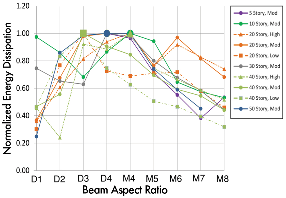
In these studies, nonlinear response history analyses were carried out using spectrally matched ground motion records on various coupled shear wall archetypes. Archetypes ranged from 5 to 50 stories in height and considered a range of longitudinal reinforcement ratios in the coupling beams and the shear walls. The results of these analyses are presented in Figure 3. The x-axis represents the aspect ratio (clear span-to-total depth) of the coupling beams. D designates a diagonally reinforced beam design, and M designates a moment frame beam design. The quantity on the y-axis is the percentage of total system energy dissipation in the coupling beams alone. The resulting trend shows the coupling beams dissipating the majority of system energy between aspect ratios of 2 and 5.
The primary characteristics of a ductile coupled shear wall system were found to be governed by geometry. Squat walls were too stiff to allow sufficient story drift for coupling beams to become inelastic. For this reason, shear walls in the DCSW system need a total height-to-length aspect ratio of no less than 2.0. Squat coupling beams were found to over-couple the seismic force-resisting system, leading to significant energy dissipation in the shear walls. As such, coupling beams in DCSW systems need to have length-to-total-depth aspect ratios of no less than 2.0 in all cases.
Very slender coupling beams, designated as having aspect ratios greater than 5.0, are too weak to contribute sufficient hysteretic energy dissipation and are allowed in no more than 10% of the levels of the building. Lastly, coupling beams conforming to these geometric constraints must be present at all levels and are required to develop 1.25fy at each end to dissipate the intended amount of energy. This last requirement is intended to preclude using fixed-pinned coupling beams that have been utilized where insufficient length exists to develop the coupling beam reinforcement into the adjacent shear wall.
ACI 318-19, Section 2.3 – Terminology, defines structural wall, ductile coupled as a seismic force-resisting-system complying with Section 18.10.9. The requirements discussed above are found in Section 18.10.9.
ASCE 7-22 Provisions
Issue Team (IT) 4 of the Provisions Update Committee (PUC) of the Building Seismic Safety Council (BSSC) developed a proposal to add three line items to ASCE 7-16 Table 12.2-1, featuring the ductile coupled wall system of reinforced concrete (see Table).
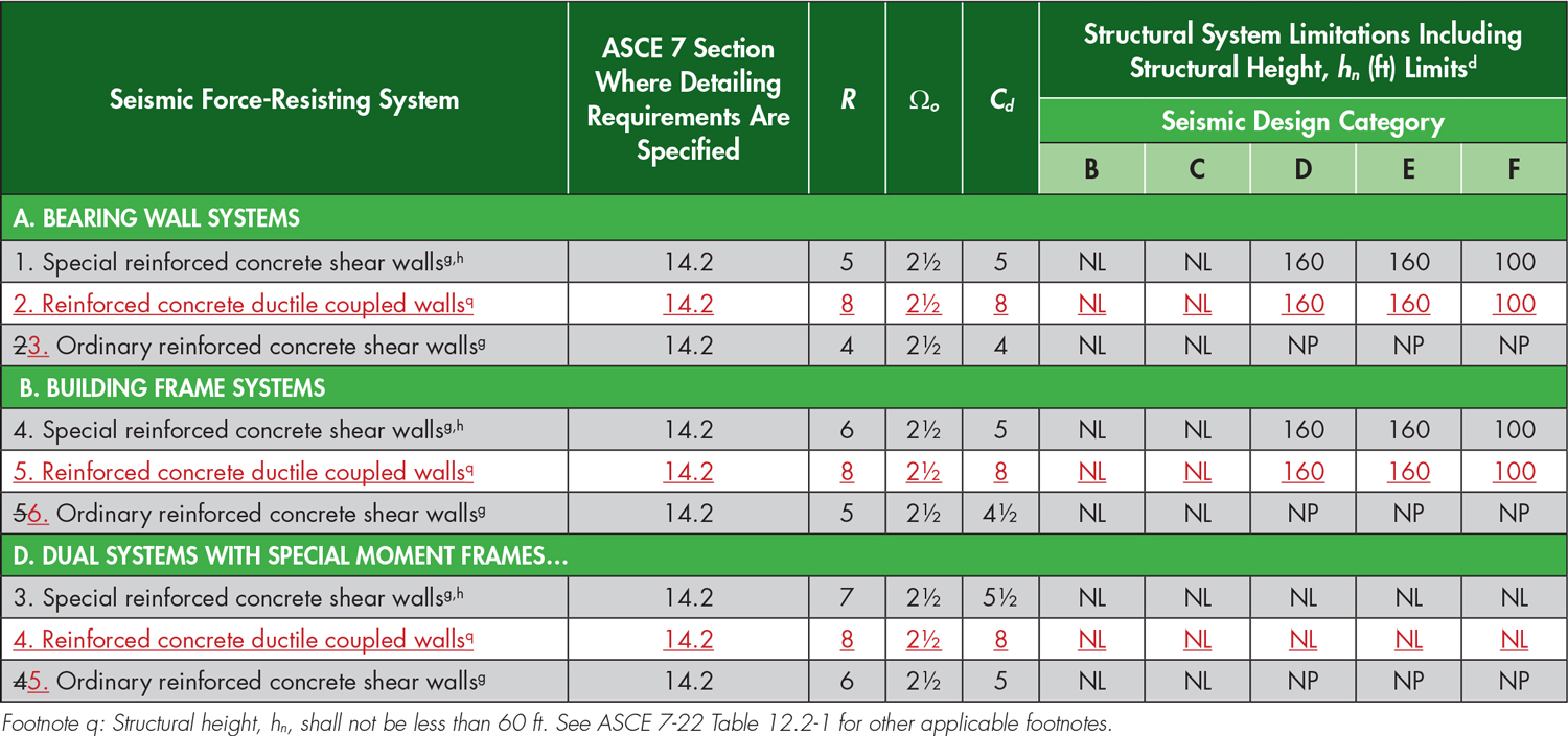
The line items are under A. Bearing Wall Systems, B. Building Frame Systems, and D. Dual Systems with Special Moment Frames. Based on a FEMA P-695 study (FEMA, 2009), R = 8, Cd = 8, and Ωo = 2.5 were proposed for all three line items. The height limits are the same as for corresponding uncoupled isolated wall systems. A minimum height limit of 60 feet is imposed on seismic force-resisting systems featuring ductile coupled walls because this system is simply not efficient for low-rise multistory buildings.
FEMA P695 Studies
The proposed response modification factors for seismic force-resisting systems featuring reinforced concrete ductile coupled shear walls were validated (Tauberg et al., 2019) using the FEMA P695 methodology. A series of forty-one ductile coupled shear wall buildings were designed using a range of variables expected to influence the collapse margin ratio, with the primary variables being building height (i.e., 6, 8, 12, 18, 24, and 30 stories), wall cross-section (i.e., planar and flanged walls), coupling beam aspect ratio (ln/h) ranging from 2.0 to 5.0, and coupling beam reinforcement arrangement (i.e., diagonally and conventionally reinforced).
There have been four significant ACI 318-19 changes, all adopted in the FEMA P695 study:
- 18.10.3.1 (shear amplification) – would typically require design shear (required shear strength) Vu to be amplified by a factor of up to 3 (similar to New Zealand, Canada).
- 18.10.6.4 – requires improved wall boundary and wall web detailing, i.e., overlapping hoops if the boundary zone dimensions exceed 2:1, crossties with 135-135 degree hooks on both ends, and 135-135 degree crossties on web vertical bars.
- 18.10.6.2(b) (Check on mean top-of-wall drift capacity at 20% loss of lateral strength) – requires a low probability of lateral strength loss at MCE-level hazard.
- 18.10.2.4 – requires minimum wall boundary longitudinal reinforcement to limit the potential of brittle tension failures for lightly reinforced walls.
For details on these important changes, reference can be made to Ghosh, Taylor (2021a, 2021b).
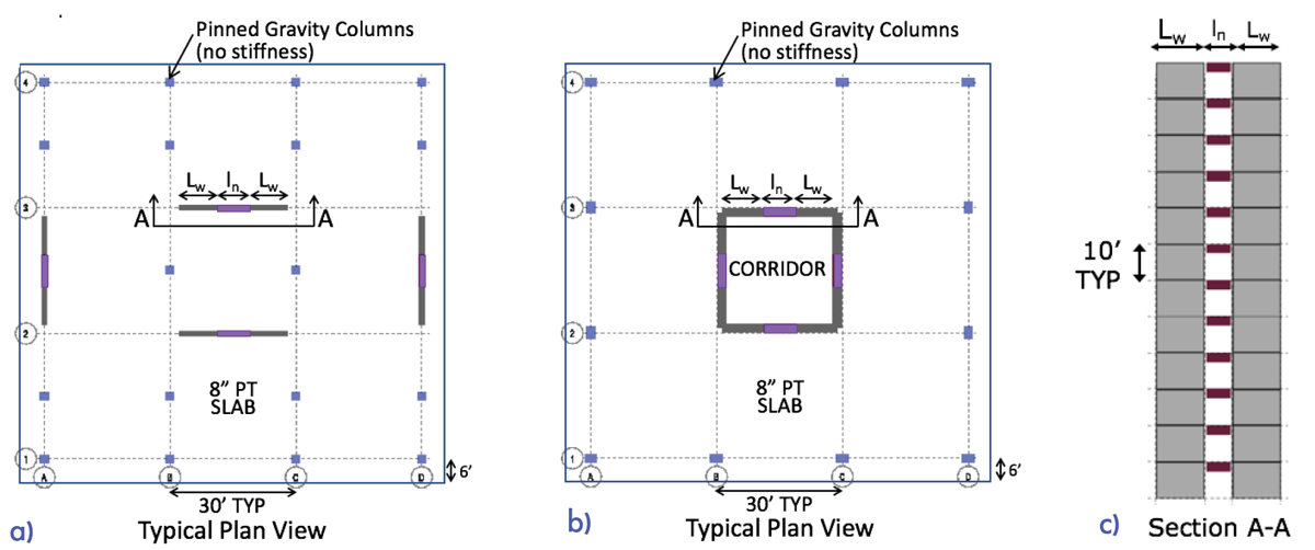
The range of variables was chosen considering those used to define a DCSW system in ACI 318-19. The resulting designs have the minimum wall area (length and thickness) required, which is governed by shear amplification and the requirement that walls sharing a common shear force not exceed a shear stress of 8√f´cAcv (where Acv = gross area of concrete section bounded by web thickness and length of section in the direction of shear force considered and f´c = the specified compressive strength of concrete). Typical floor plans and a wall elevation view are presented in Figure 4.
A conservative approach was used to define collapse for the FEMA P695 study, i.e., the collapse was taken as a 20 percent drop in lateral strength. This approach is conservative because the loss of axial load carrying capacity typically does not occur until lateral strength drops more significantly, e.g., an 80 percent drop. In some studies, axial failure has been assumed to occur at a specified roof drift ratio, which has been typically 4 to 5 percent (Kircher et al. 2010), whereas, in this study, the conservative approach used resulted in roof drift ratios that were typically not more than 3 percent.
A system overstrength factor of Ωo = 2.5 is proposed based on nonlinear static pushover analysis results indicating that the mean overstrength values of the performance groups range from 1.31 to 2.13. The proposed response modification factor, R = 8, was validated based on incremental dynamic analysis results indicating that the mean Adjusted Collapse Margin Ratio (Tauberg et al. 2019) values of the performance groups ranged from 1.99 to 2.84, corresponding to collapse probabilities of less than ten percent, based on using a conservative definition of collapse as noted above. The deflection amplification factor of Cd = 8 is proposed based on damping considerations and the assessment of median roof drift responses from design level earthquakes compared to design roof drifts. Overall, the results of this study suggest that an overstrength factor Ωo = 2.5, a response modification factor R = 8, and a deflection amplification factor Cd = 8 are appropriate seismic design parameters for RC Ductile Coupled Wall systems that are designed per ASCE 7-22 and ACI 318-19 provisions.
Design Example
A 22-story reinforced concrete residential building is designed (Ghosh 2021) following the requirements of ASCE/SEI 7-22 and ACI 318-19 in the recent FEMA Publication P-2192, 2020 NEHRP Recommended Seismic Provisions: Design Examples, Training Materials, and Design Flow Charts (Figure 5). The building consists of a flat plate-column gravity system with a central core formed by four reinforced concrete coupled structural walls acting as the seismic force-resisting system. The structural walls are designed as Ductile Coupled Reinforced Concrete Shear (Structural) Walls. This complete design example is expected to be a valuable resource to the practitioner.
Conclusion
This article discusses the recognition of a ductile coupled concrete shear wall system as a distinct seismic force-resisting system in ASCE 7-22 Table 12.2-1. In addition, the ductile coupled concrete shear wall system is defined in ACI 318-19.
This development should pave the way for more widespread use of this efficient system in U.S. buildings assigned to high seismic design categories.■
References
ACI (2019). Building Code Requirements for Structural Concrete, ACI 318-19 and Commentary, ACI 318R-19, American Concrete Institute, Country Club Hills, MI.
ASCE (2022). Minimum Design Loads and Associated Criteria for Buildings and Other Structures, ASCE/SEI 7-22, American Society of Civil Engineers, Reston, VA.
Bertero, V.V., (1977). “Seismic Behavior of R/C Wall Structural Systems,” Proceedings, Workshop on Earthquake-Resistant Reinforced Concrete Building Construction, University of California, Berkeley, July, pp. 323-330.
CSA Group (2014). Design of Concrete Structures, A 23.3.14, Mississauga, Ontario, Canada.
FEMA (2009). Quantification of Building Seismic Performance Factors, FEMA P-695, prepared by the Applied Technology Council for the Federal Emergency Management Agency, Washington, D.C., June 2009.
Ghosh, S. K., and Dasgupta, P., (2021). Ductile Coupled Shear Wall System as a Distinct Seismic Force-Resisting System in ASCE/SEI 7-22, Chapter 4, FEMA Publication P-2192-V1, Federal Emergency Management Agency, Washington, D.C., November, pp. 126-171.
Ghosh, S. K., and Taylor, A.W. (2021a). “Changes in ACI 318 Code Provisions for Earthquake-Resistant Structures, Part 1,” Concrete International, American Concrete Institute, Country Club Hills, MI, March, pp. 45-49.
Ghosh, S. K., and Taylor, A.W. (2021b). “Changes in ACI 318 Code Provisions for Earthquake-Resistant Structures, Part 2,” Concrete International, American Concrete Institute, Country Club Hills, MI, April, pp. 37-44.
Kircher, C. A., Deierlein, G. D., Hooper, J. D., Krawinkler, H., Mahin, S. A., Shing, B., and Wallace, J. W. (2010). Evaluation of the FEMA P-695 Methodology for Quantification of Building Seismic Performance Factors, Report NIST GCR-10-917-8, National Institute of Standards and Technology, Gaithersburg, MD, November 15, 268 pp.
Standards New Zealand (2006). Concrete Structures Standard, NZS 3101. 1&2, Wellington, New Zealand.
Tauberg N., Kolozvari K., Wallace J.W., (2019). Ductile Reinforced Concrete Coupled Walls: FEMA P695 Study, Final Report, University of California, Los Angeles, CA, July, 106 pp.