
Anchor Channels in Industrial Structures, Bridges, and Tunnels
Anchor channels with channel bolts enable the robust anchorage of components to reinforced concrete structures. State-of-the-art systems comprised of anchor channels and channel bolts, also commonly known as anchor channels, handle static, seismic, and fatigue loads in any direction. Installing components with channel bolts is fast and easy even under adverse conditions, where wind, water, and confined space entry restrict work activities, particularly with electrical equipment needed for welding, or when overhead installation may be too exhaustive for the installer due to long installation times.
History of Anchor Channels
Anchor channels are a success story that began over 100 years ago, triggered by the global spread of reinforced concrete in building structures. Originally, anchor channels were invented to fasten components to concrete in industrial structures, such as transmission belts suspended from the ceilings. Therefore, they were known as a means for suspending objects from reinforced concrete structures (Figure 1).
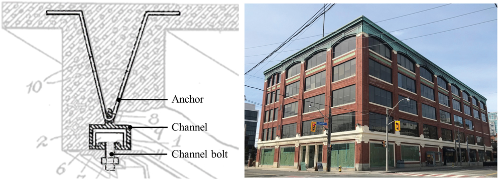
Anchor channels consist of steel anchors (for example, round anchors, I-anchors, V-anchors, etc.) and C-channels, fabricated as one unit mostly by forging or welding. Anchor channels are cast flush in reinforced concrete elements and, after the concrete has reached its design strength, become a robust anchorage when utilized with matching channel bolts, known as T-bolts.
Installation
The installation of anchor channels and channel bolts is a simple procedure (Figure 2). First, the anchor channel is attached with nails or screws to the wood formwork before concrete placement. The anchor channels contain a removable filler material that prevents concrete from entering the channel. After the concrete has hardened and the formwork is stripped, the filler material is easily removed. Next, channel bolts are inserted into the slot of the anchor channel and turned until they stop – one edge of the channel bolt head is slightly larger than the internal clear spacing between the channel walls, preventing the bolt from spinning inside the channel. The head of the channel bolt is then 90° to the direction of the anchor channel. The channel bolt can be positioned anywhere along the slot, enabling the installation of components at the exact point where needed.
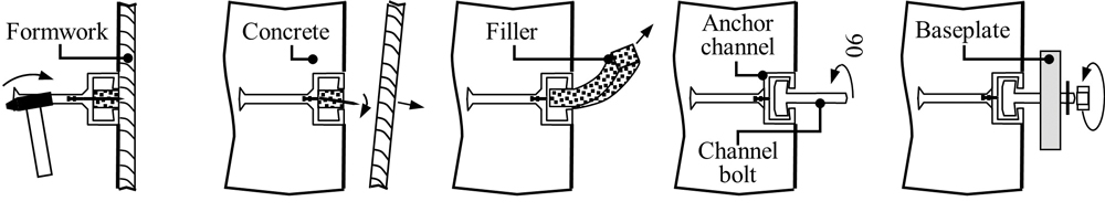
When steel formwork is used, often in bridge and tunnel construction, blind rivets (also known as pop rivets) with special installation cones are used to attach the anchor channel. This attachment method ensures that the anchor channels do not shift during placement and consolidation of the concrete. The anchor channel may be connected to an electrical grounding system before the concrete placement. Thus, any component mounted using channel bolts can be electrically grounded. Anchor channels with channel bolts have further benefits:
- Load transfer in any direction due to mechanical interlock (between bolt and channel as well as between anchor and concrete).
- Tolerance compensation by adjusting the position of the channel bolt along the anchor channel.
- Minimal training is required for installation of the anchor channel and channel bolt.
- A simple mechanical connection option avoids costly field welding, which often comes with quality and safety risks.
- No inaccurate and time-consuming drilling for anchoring, and thus, no silica dust and cutting of reinforcing bars.
- No external power sources or ventilation equipment is needed for installation.
- Provides immediate load-carrying capability.
- A long-established system allows for timely scheduling of anchor channels and channel bolts to the job site.
- Easy positional adjustment, maintenance, and future upgrades of attached components are straightforward.
- A sustainable construction methodology without expiration dates, yet 100% recyclable when the structure is demolished.
Applications
Over time, the vertical layout of early industrial reinforced concrete structures, characterized by a limited height of the individual story (Figure 1), morphed into a horizontal layout with a single, high story. Consequently, some equipment was best mounted in reinforced concrete columns and walls, increasing the application of anchor channels and channel bolts. The use of anchor channels has spread to all types of concrete structures. Today anchor channels are used in wastewater plants, water plants, dams, and power plants, as well as (supertall) high-rise buildings for the connection of curtain wall facade elements. Another important field of application is bridges and tunnels.
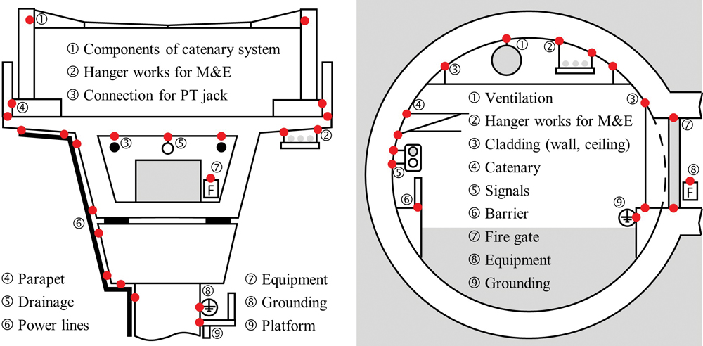
Figure 3 shows example applications used for bridge and tunnel projects past and present. Anchor channels are produced at any length up to twenty feet and curved to any radius needed. Anchor channels and channel bolts are available in hot-dipped galvanized (HDG) carbon steel and stainless steel for installations exposed to highly corrosive environments. Some examples are bridges and tunnels exposed to de-icing salts or high ambient salinity along coastal areas. The application possibilities are innumerable – for example, installations in prestressed concrete spun catenary poles used for railway power lines or precast segments used for lining of bored tunnels. Solutions are available to ensure that tunnel precast segments with cast-in anchor channels can be handled with vacuum lifters which are devices to hoist using suction cups.
Longitudinal Load Transfer
Initially, anchor channels were designed to be loaded in pure tension, N, only. However, most connections are also loaded in shear perpendicular to the channel axis, Vy. In many applications, the connection is also loaded in shear along the axis of the channel, Vx (Figure 4). By tightening a conventional channel bolt against the anchor channel, a frictional force from the clamping allows limited longitudinal loads. The need for a robust axial load capability initiated the invention of the notching channel bolt in 1985. These bolts have teeth that ‘bite’ into the channel lip when installed and torqued as specified, generating notches and thus mechanical interlock. However, notching channel bolts have a high installation torque sensitivity: the required installation torque, Tinst, for example, 130 pounds force-foot for a 5⁄8-inch channel bolt, is considerable. An installation torque accidentally reduced by 50% may almost cut the longitudinal load capacity by half (Figure 4).
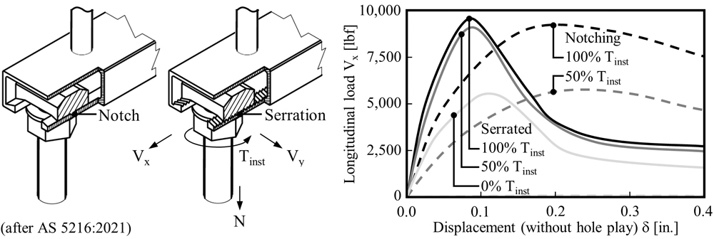
For this reason, channel bolts with serrated heads and anchor channels with matching serrated lips were developed in the 1990s. This connection system of serrated anchor channels with matching serrated channel bolts allows the transfer of significantly higher longitudinal loads by mechanical interlock because of their low installation torque sensitivity (Figure 4). The longitudinal load capacity is reduced by only about 5% if the applied installation torque was erroneously only 50%. Even if the bolt is just snug tightened, serrated channel bolts transfer significantly more than half of the original longitudinal load. Notching channel bolts, on the contrary, transfer virtually no longitudinal load without installation torque applied. Moreover, longitudinal displacements under longitudinal load are generally smaller for serrated channel bolts compared with notching channel bolts.
Design
Anchor channels and channel bolts are designed like concrete anchors using design requirements codified in the American Concrete Institute (ACI) 318, Building Code Requirements for Structural Concrete and Commentary. Additional design provisions are given in AC232, Acceptance Criteria for Anchor Channels in Concrete Elements, published by the International Code Council Evaluation Service (ICC-ES). ACI 533.5, Guide for Precast Concrete Tunnel Segments, provides further advice for the use of anchor channels in tunnels. The design of anchor channels and channel bolts is complex and requires product-specific data from a qualification testing protocol. The design procedure involves the calculation of twenty possible failure mode capacities and their interaction. Any failure mode can control the design; that is, the lowest calculated capacity determines the design capacity.
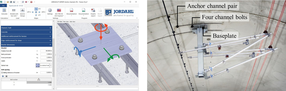
Proprietary design software (Figure 5), developed to facilitate extensive calculations, enables the engineer to carry out the structural analysis of qualified products thoroughly and efficiently. Typically, the design software, e.g. JORDAHL® EXPERT, also supports the analysis of anchor channel pairs, often used to fix baseplates with four channel bolts (Figure 5). In addition, interfaces allow the data exchange between the design software and Building Information Modeling (BIM) software. This is important since BIM has become more critical and sometimes mandatory, particularly for infrastructure projects.
Qualification
AC232 is primarily a guideline providing acceptance criteria for qualification testing of anchor channels to receive an Evaluation Service Report (for example, ESR-2854), containing the product-specific data required for its design. While static qualification is standard, seismic qualification is optional but typically required for important infrastructure projects like bridges and tunnels – even in regions of low seismicity. Anchor channels can be seismically qualified only if they can transfer load in the longitudinal axis of the anchor channel by mechanical interlock. Note that compression loads normal to the concrete surface are taken by direct load transfer from the baseplate.
Tension and shear load tests are conducted on anchor channels cast in concrete test members for qualification testing. Test members are unreinforced to evaluate the load performance for the worst-case scenario. Apart from additionally placed anchor reinforcement, any steel reinforcement is neglected when calculating the design load capacity of the connection. For this reason, replacing the steel reinforcing bars with carbon fiber (CFRP) or glass fiber (GFRP) bars, used to prevent magnetic interference and accelerated corrosion of embedded steel reinforcement, does not influence the calculated design load.Moreover, research has shown that the load performance of anchor channels cast in fiber reinforced concrete (FRC), popular for tunnel segments, is better than for anchor channels cast in conventionally reinforced concrete. Therefore, anchor channels cast in FRC can be designed using the same design assumptions.
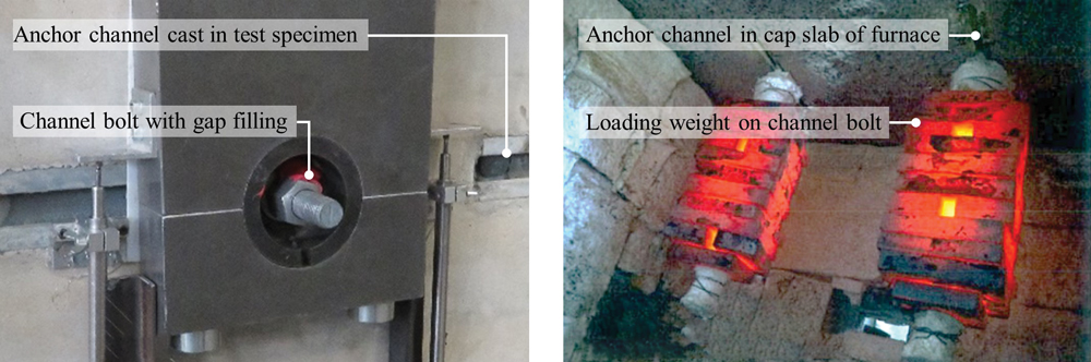
The fatigue and fire performance of concrete anchors, including anchor channels, is not mandatory though may be relevant, particularly for applications in bridges and tunnels. The fatigue and fire qualification of concrete anchors is not fully regulated yet but can be tested (Figure 6) and reported if required.
Fatigue assessment may be critical for some connections at bridges and tunnels because of the repeating structural vibrations and pressure waves. Fatigue assessment of anchor channels and channel bolts in shear requires that the gap between the anchor channel and channel bolt and the gap between the channel bolt and baseplate is filled with adhesive to reduce the stress cycle. To this end, special gap filler sets have been developed, including a special nut for the injection and an insert to be installed together with the channel bolt before mounting the baseplate. The fatigue performance depends on the geometry, for example, at the joining of anchor and channel, and on the material selection and production technology. The fatigue strength of a poorly engineered anchor channel may be only a fraction of another anchor channel of the same size and static strength.
Fire rating of concrete anchors has recently moved into focus because fastened components are often relevant to fire safety. For fire rating testing, anchor channels are cast into the underside of a slab which forms the cap of a fire furnace. After dead load weights are connected to the channel bolts, the fire furnace is typically heated according to a standard temperature curve (STC), as defined in the International Standard ISO 834-1, Fire-Resistance Tests – Elements of Building Construction – Part 1, General Requirements (almost 2000°F after 120 minutes), which serves as an alternative to the ASTM E119, Standard Test Methods for Fire Tests of Building Construction and Materials. The time-to-failure is measured for a simplified yet conservative evaluation method to define design strengths as a function of required fire resistance time.
Summary
Anchor channels with their channel bolts are an iconic fastening system for heavy and sustained static, and seismic and fatigue loads. Only products with stringent, independent third-party evaluations according to the AC232 acceptance criteria have a recorded Evaluation Service Report (ESR) issued by the ICC-ES. The ESRs certify their suitability for static and seismic applications. AC232 amends the provisions for concrete anchors stipulated in the ACI 318 reinforced concrete code to ensure that the system can be designed according to the state-of-the-art. Free design software can help the structural engineer design thoroughly and efficiently. Properly designed, qualified anchor channels with channel bolts allow robust anchoring in concrete structures, including bridges and tunnels.■