
Using SDPWS 2021 and ASCE 7-16
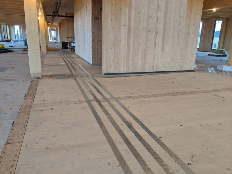
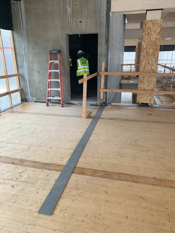
Cross-laminated timber (CLT) has become increasingly prominent in building construction and can be seen in buildings worldwide (Figure 1). Specifically, CLT floor and roof panels have become relatively commonplace as a primary gravity force-resisting component. Now, with the availability of the 2021 Special Design Provisions for Wind and Seismic (SDPWS 2021) from the American Wood Council (AWC), U.S. designers have a standardized path to utilize CLT floor and roof panels as a structural diaphragm.
AWC SDPWS 2021
SDPWS 2021 is the first edition to provide direct provisions for CLT use as an element in a diaphragm or shear wall. To differentiate between CLT and light-frame lateral force-resisting systems, it adopts the terminology sheathed wood-frame for light-frame diaphragms (SDPWS §4.2) and shear walls (SDPWS §4.3). In addition, it includes new sections for CLT diaphragms (SDPWS §4.5) and shear walls (SDPWS §4.6). The 2021 International Building Code (IBC) references SDPWS 2021.
Shear Capacity
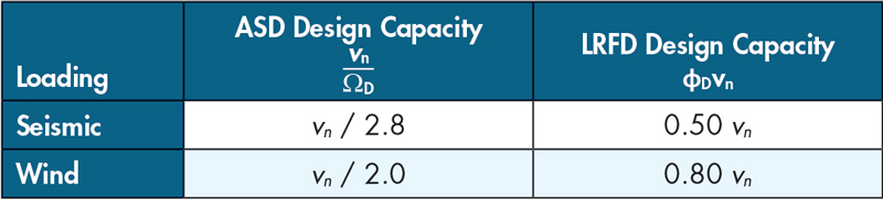
SDPWS 2021 has a single nominal shear capacity for each set of construction details, vn, defined in §4.1.4 for use with both wind and seismic design. From this nominal shear capacity, the Allowable Stress Design (ASD) and Load and Resistance Factor Design (LRFD) wind and seismic design capacities are determined by dividing by the ASD reduction factor, ΩD, or multiplying by a resistance factor, φD, for LRFD design, respectively, as summarized in Table 1.
CLT Diaphragms
SDPWS 2021 §4.5 contains new provisions for the design of CLT diaphragms. When using these provisions, designers use an engineered approach to meet the required design loads defined by the building code (IBC) and ASCE 7, Minimum Design Loads and Associated Criteria for Buildings and Other Structures.

When designing CLT diaphragms, the general requirements for all wood systems in SDPWS §4.1 apply, including limits on when wood members can be used to resist seismic forces from concrete or masonry walls in §4.1.5. However, the requirements specific to sheathed wood-frame diaphragms in SDPWS §4.2 do not apply.
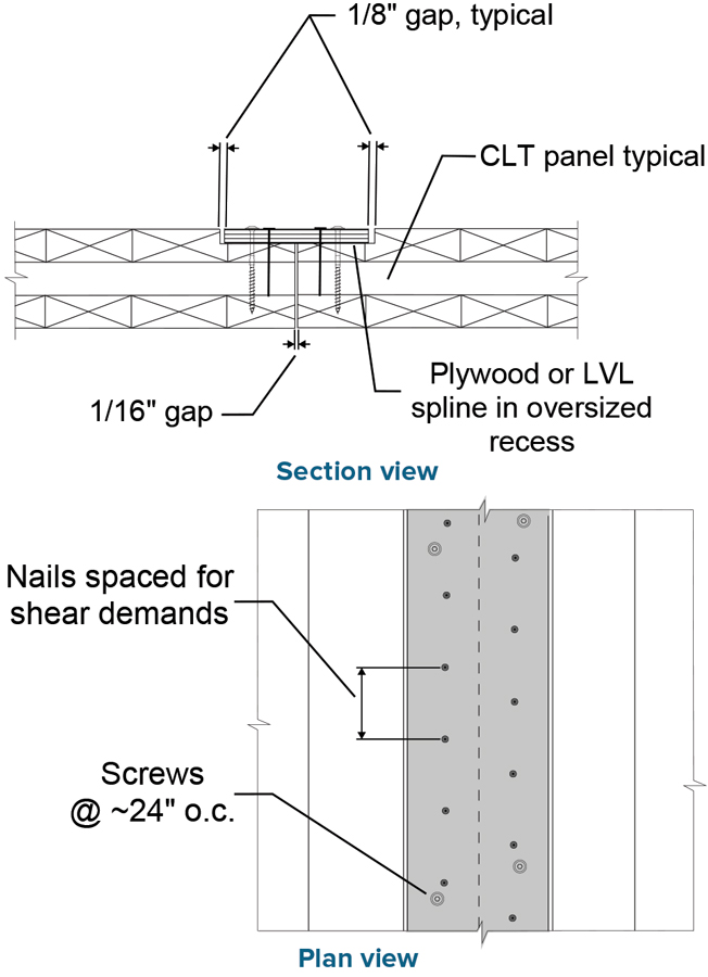
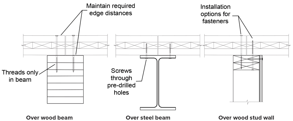
SDPWS §4.5.4 Item 1 requires that diaphragm shear forces transfer between adjoining CLT panels and between CLT panels and boundary elements through dowel-type fasteners in shear. Dowel-type fasteners include nails, wood screws, lag screws, and bolts. In practice, nails and proprietary self-tapping screws are most commonly used in CLT diaphragm connections. SDPWS §4.5.4 Item 2 does not permit the diaphragm shear connections to transfer the diaphragm tension forces, such as at chords and collectors. Figure 2, Figure 3 and Figure 4 show examples of diaphragm shear connections.
For diaphragm shear connections, the capacities of the dowel-type fasteners (nails and screws) in shear, Z, are calculated using the yield mode equations of the National Design Specification® (NDS®) for Wood Construction §12.3.1. Mode IIIs or Mode IV is required to control the capacity of the diaphragm shear connections. An adjusted design capacity, Z*, defined in SDPWS §4.5.4 Item 1, is the basis for the nominal diaphragm shear capacity of the connection. Z* is similar to the adjusted design capacity, Z´, in NDS Table 11.3.1, except the ASD and LRFD-specific adjustment factors, CD, KF, φ, and λ, are not applied.
Z* = Z x CM Ct Cg CΔ Ceg Cdi Ctn
The nominal shear capacity per fastener is:
Vn = 4.5 Z*
A regular on-center spacing, s, in inches, is often specified for fasteners in such connections. Calculating the nominal unit diaphragm shear capacity (plf) of such a connection is as follows:
vn = 4.5 Z* (12 in/ft) / s
The requirements and calculation method apply to the connections transferring diaphragm shear, including panel-to-panel, panel-to-chord, and panel-to-collector connections. Figure 5 shows an example of a CLT diaphragm with components and connections labeled for discussion. The diaphragm shear connections shown include (a) panel-to-panel connections not over framing, (b) panel-to-panel connections over a beam, (c) panel-to-collector connections, and (d) panel-to-chord connections.
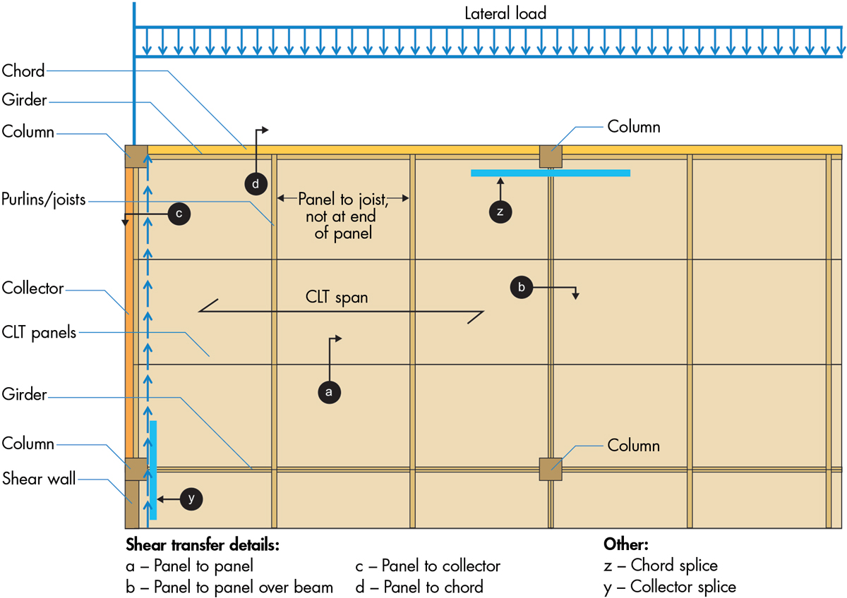
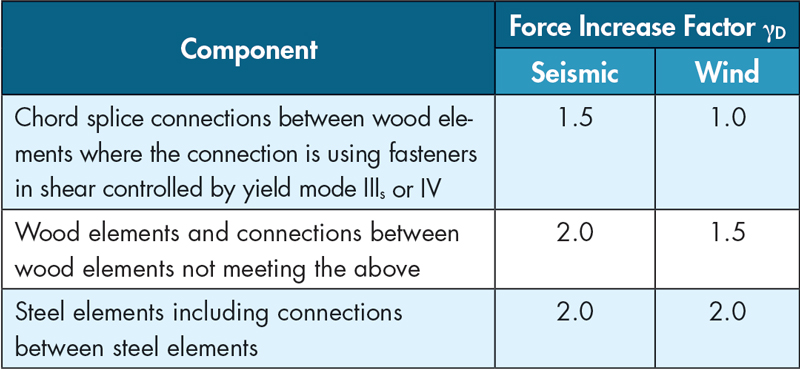
The chords, collectors and their connections, (y) and (z) in Figure 5, and other structural components transferring shear, such as the CLT panels themselves, have different design requirements. These components and connections must be designed to a higher required capacity using a force increase factor applied to the diaphragm design force. The required force increase factors are found in SDPWS §4.5.4 Item 3, including Exceptions 1 and 2, and are summarized in Table 2.
The capacities of these diaphragm components are calculated using the provisions of the applicable material design method. The design capacities of wood chords, collectors, and their connections are calculated using the NDS, not the SDPWS nominal capacity (4.5 Z*) and reduction factors.
Important Detailing Considerations
CLT or Framing as Boundary Element
Boundary elements for diaphragms include chords, collectors, their splices, and their connections to the vertical lateral force-resisting system (VLFRS). Boundary elements in CLT diaphragms can include steel straps, framing components supporting the CLT such as steel or timber beams, or the CLT panels themselves. For CLT diaphragms supported by light-frame walls, the top plates of the walls below can act as chord and collector elements.
In practice, it is often advantageous to use CLT panels, coupled with top side metal straps at panel breaks, as the primary chord and collector elements. This is especially true for glulam-supported floor systems, as it can be challenging to transfer chord/collector demands across beam-to-column connections.
Connection Gaps and Tolerances
The details shown in Figure 3 and Figure 4 may be constructed with measurable gaps between the panels. These gaps may result from fabrication tolerances and intentional under-sizing of the panels for erection tolerances. When panels meet over framing, as shown in Figure 4, and the framing functions as a shear transfer component between the panels, gaps are of little consequence to the diaphragm shear behavior. However, if CLT panels act as a boundary element and panel-to-panel bearing is used to transfer compressive axial forces, the design must account for the presence of gaps. In such cases, excessive gaps need to be filled with a non-compressible material in the boundary element region to provide an axial load path.
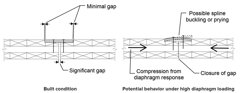
When using a recessed spline to transfer diaphragm shear forces between CLT panels, as seen in Figure 3, there are two types of gaps – gaps between CLT panels and gaps between the shoulders of the recess in the CLT panel and the spline placed in the recess. Under design-level loading events, CLT panels in diaphragms mostly behave as rigid elements; however, they can shift in response to applied forces, creating deformations at the panel-to-panel connections. In areas of local compression between panels, if the compression is resisted by the spline, as shown in Figure 6, it may create a prying or buckling reaction in the spline, which may reduce the shear capacity of the spline connection.
It is recommended that, in spline connections, the gap between panels be not more than the sum of the gaps on each side of the spline to mitigate this behavior. This allows the panel gap to close and achieve bearing before the spline side member gaps close completely. To follow this recommendation, specify that the width of the recess in the CLT panels be larger than the specified width of the spline material. For example, a convenient set of dimensions is a 5⅞-inch-wide plywood spline with a ⅛-inch gap on each side and a nominal gap of 1⁄16-inch between panels.
Design Loads and Force Increase Factors
The SDPWS CLT diaphragm design method requires designing the diaphragm shear connections to the diaphragm design forces specified by the building code, labeled here as Fdesign. The 2021 IBC references ASCE 7-16 for the derivation of the appropriate wind and seismic diaphragm design forces and requirements. Following the SDPWS, the remaining components of the diaphragm are designed to increased diaphragm design forces, γDFdesign.
A common question regarding CLT diaphragm design is how to use the SDPWS force increase factors in conjunction with various amplification factors of ASCE 7 for seismic design. For seismic design, calculate the diaphragm design force following ASCE 7-16 §12.10.1.1, which can be described in equation form as:
Fdesign = max(Fpx,Fx) + Ω0Fx_transfer
Where Fpx is the inertial diaphragm design force calculated using ASCE 7-16 Eq. 12.10-1 through 12.10-3, Fx is the force in the diaphragm from the structural analysis of the seismic lateral force-resisting system, and Fx_transfer is the transfer force through the diaphragm, when applicable, from one VLFRS component to another. These diaphragm transfer forces occur at out-of-plane offset irregularities of the VLFRS, such as horizontal structural irregularity Type 4 of ASCE 7-16 Table 12.3-1.
Following standard practice, as presented in the Structural Engineers Association of California’s Structural/Seismic Design Manual Vol 1, the redundancy factor, ρ, of ASCE 7 is equal to 1.0 to determine the non-transfer design forces on the diaphragm. Therefore ρ > 1.0 is not included in the diaphragm design force, Fdesign.
Where a significant seismic diaphragm transfer force, Fx_transfer, occurs, ASCE 7-16 §12.10.1 can require applying the vertical seismic force-resisting system overstrength factor, Ωo, to the seismic transfer forces within the diaphragm design force. In this case, the overstrength factor, Ωo, is within Fdesign for the diaphragm design and thus cumulative with the SDPWS force increase factor γD:
γDFdesign = γDmax(Fpx,Fx) + γDΩ0 Fx_transfer
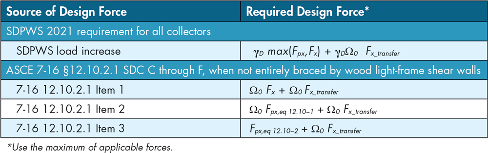
For structures in Seismic Design Categories C through F, the required design forces for collectors potentially include amplification by Ωo per ASCE 7-16 §12.10.2. However, if the structure is entirely braced by light-frame wood shear walls, the exception to §12.10.2 applies, and Ωo does not apply to the collector design. Otherwise, the collector, collector splice connections, and collector connections to the VLFRS must be designed to the maximum of the three enumerated force levels in §12.10.2 and the increased diaphragm design forces required by SDPWS 2021, shown in Table 3. As the load increase factor in SDPWS 4.5.4 Item 3 applies to the diaphragm design forces, the amplification of forces by Ωo per ASCE 7-16 §12.10.2 for collector design is not cumulative with the load increase factor, γD, of the SDPWS. This is different than amplification of diaphragm transfer forces by Ωo per ASCE 7-16 §12.10.1, as the transfer forces are part of the diaphragm design forces.
For structures in Seismic Design Categories D, E, and F with certain structural irregularities, the design forces for collectors and connections between the diaphragm and vertical elements may need to be increased by 25% per ASCE 7-16 §12.3.3.4. Similar to the Ωo of §12.10.2, this is an increase in the required strength of specific components and not an increase in the diaphragm design force and is therefore not included in Fdesign. For collectors, collector splices, and connections to the VLFRS, γD is 2.0 for seismic design. Therefore, the design force, γD Fdesign, required by SDPWS, will always be greater than 1.25 Fdesign when required by ASCE 7. For the CLT diaphragm shear connections from the CLT panels directly to the collectors and VLFRS, γD does not apply in the SDPWS; therefore, these shear connections must be designed to 1.25 Fdesign if triggered in ASCE 7-16 §12.3.3.4. Figure 7 shows an example of a collector strap from a CLT diaphragm to core walls.
Diaphragm Flexibility
In ASCE 7, several specific diaphragm types can qualify prescriptively as flexible or rigid. CLT diaphragms are not included in the prescriptive categories. ASCE 7 does allow a diaphragm to be idealized as flexible when:
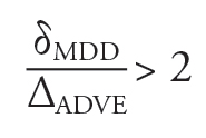
Where δMDD is the maximum in-plane diaphragm deflection; ΔADVE is the average deflection of adjoining vertical elements of the VLFRS. ASCE 7 does not provide a method to idealize a diaphragm as rigid by analysis; however, IBC §1604.4 and SDPWS §4.1.7 address this approach. Given the large size and high in-plane stiffness of CLT panels, it is usually the case that CLT diaphragms can be idealized as rigid if used with wood structural panel shear walls or steel or concrete moment frames. When CLT diaphragms are used with concrete shear walls or steel braced frames, sometimes the diaphragms can be idealized as rigid and sometimes as flexible. Alternative options include a semi-rigid or an envelope analysis.
Further Information
This article provides a brief summary of the new CLT diaphragm provisions in SDPWS 2021 and recommendations from the authors on their implementation. The upcoming CLT Diaphragm Design Guide published by WoodWorks will provide detailed information, including the design of collector and chord details, full examples, and pre-calculated tables of connection capacities. For questions and free technical support related to mass timber and light-frame wood buildings, contact the WoodWorks regional director nearest you (woodworks.org/project-assistance) or email help@woodworks.org.
Acknowledgments
Primary funding for the development of this document was provided by the U.S. Endowment for Forestry and Communities and USDA Forest Service.■
Portions of this article were previously posted on the WoodWorks website, March 2022. It is reprinted with permission.