
Adoption of IBC 2018 Shakes Up Storm Shelter Requirements
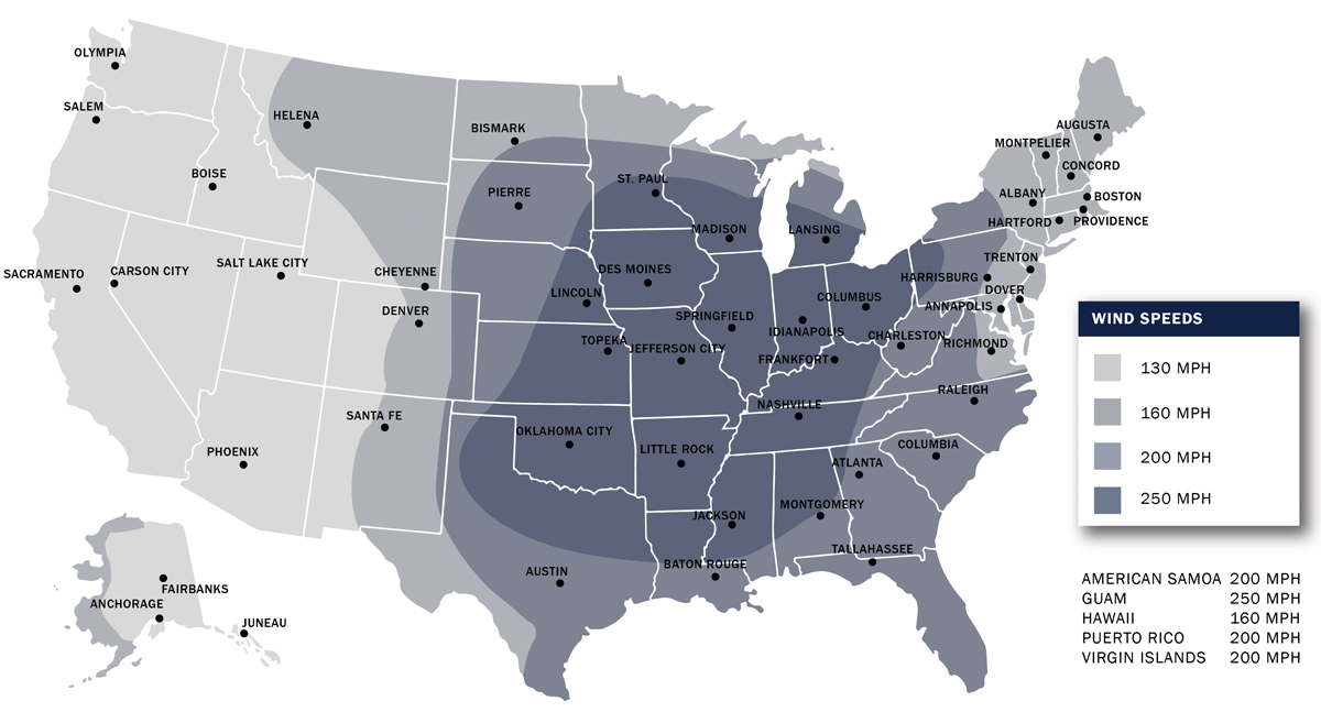
With the 2018 Edition of the International Building Code (IBC) being adopted in more jurisdictions across the country, some designers in storm-prone areas may be surprised that their next project requires a storm shelter. Section 423 of IBC 2018 now requires that structures housing critical emergency operations and certain Occupancy E buildings incorporate storm shelters in accordance with the International Code Council and National Storm Shelter Association’s Standard for the Design and Construction of Storm Shelters (ICC 500). The code requires projects such as police stations and elementary schools (with occupant loads over 50) located in parts of the country with potential tornado wind speeds of 250 mph to incorporate a storm shelter. Although some designers may think their projects are not typically prone to tornados, this requirement affects a large portion of the country, as shown by the dark shaded area in ICC 500-2014, Figure 304.2(1) (Figure 1).
Outside of the prescriptive design requirements such as occupant load and site location, the structural requirements can be challenging to meet and even more challenging to implement. Like all structures, creating a load path from the roof structure to the foundation is paramount for the design of storm shelters. Due to the extreme loading conditions, connections between the roof structure and the load-bearing wall system, and connections between the wall system and the foundation, need to be structurally adequate and constructible. This article highlights some of the requirements of the ICC 500, the critical elements of storm shelter design, and some typical issues that arise during construction that can be mitigated using good communication between the design team and contractor.
Terminologies
First, it is important to discuss some of the nomenclatures used for enclosures that help protect people from storms. ICC 500 uses the term storm shelter. This term refers to detached buildings or rooms/areas within host buildings designed and constructed according to ICC 500. The ICC 500 is the standard that establishes minimum requirements to safeguard the public from high winds associated with tornados and hurricanes. Technically, suppose an enclosure does not meet all of the requirements of the ICC 500 (architectural, structural, mechanical, electrical, and fire protection). In that case, it should not be referred to as a storm shelter.
The Federal Emergency Management Agency (FEMA) uses the term safe room. Similar to storm shelters, this term refers to wind-refuge areas that meet the requirements of FEMA’s Safe Rooms for Tornados and Hurricanes (FEMA P-361). FEMA P-361 has more stringent requirements than ICC 500, so different terminologies are used. FEMA P-361 states that safe rooms provide near-absolute protection for occupants during a storm event. All safe rooms are storm shelters, but not all storm shelters are safe rooms. This difference is because FEMA requires additional “Funding Criteria” above and beyond the minimum requirements of ICC 500 when FEMA funds are used to construct a safe room. Additional detail on the differences between the ICC 500 storm shelter and the FEMA P-361 safe room criteria can be found in FEMA P-361-(2021) Section A1.3.3.
ICC 500 Storm Shelter Requirements
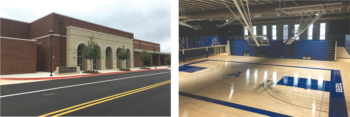
Many design professionals have been designing storm shelters for some time due to state laws. For instance, the State of Alabama began requiring storm shelters to be incorporated into all public K-12 schools beginning in 2010 (Figure 2). In addition, Alabama required storm shelters in all public 2-year and 4-year higher education institutions a year later. Now that similar requirements have been incorporated into the IBC, more design professionals and owners must become familiar with the storm shelter requirements.
ICC 500 has requirements for most design disciplines associated with a storm shelter project. Bathrooms, egress and ingress, signage, emergency power, and ventilation are just some of the non-structural requirements for a storm shelter. The architect, structural engineer, and owner should all be involved in determining the location of the storm shelter. The owner must regularly maintain storm shelter elements such as doors and operable louvers. Owners will also be involved in educating the occupants and performing drills to ensure the shelter is used correctly.
The structural requirements for storm shelters are similar to standard building design, but the loading conditions are significantly higher. For gravity loads, the roof live load is 100 pounds per square foot (psf) compared to the typical 20 psf, and increased rain loads should be considered in combination with this roof live load. In addition to the increased roof live load, the designer must also consider laydown and falling debris hazards. These additional loads would include the collapse of an adjacent structure or host building. Therefore, these loads should be added to the uniform roof live load, and impact factors for laydown and falling debris should be considered per ICC 500.
For lateral loading, loads are calculated similar to standard building design, with the following exceptions: Design wind speeds for tornados are per ICC 500 Figure 304.2(1), and similar figures are given for hurricanes; wind loads shall be based on Exposure Category C for tornado shelters, and Exposure Category B is not permitted for hurricane shelters unless excepted per ICC 500; the directionality factor, Kd, shall be taken as 1.0, and the topographic factor, Kzt, shall not exceed 1.0. The enclosure classification for storm shelters can be determined per ASCE 7, Minimum Design Loads and Associated Criteria for Buildings and Other Structures. However, atmospheric pressure change (APC) must be considered for tornado shelters. Based on experience, pressure change is typically hard to manage with venting. Therefore, most tornado shelters are designed as partially enclosed (GCpi = ±0.55), so APC can be neglected per ICC 500. Finally, shielding effects from adjacent structures cannot be considered. ICC 500 assumes that the host building and adjacent structures are destroyed during a storm event, and the shelter is fully exposed.
Besides standard building structural design, additional requirements include wind-borne debris for horizontal and vertical surfaces, connections of host building elements (non-shelter) to shelter elements, and penetration requirements. The designer should study these atypical requirements to ensure that the shelter performs effectively and protects its occupants.
Some architectural elements affect the shelter envelope, and the designer should be involved with the specification and detailing around these elements. For instance, storm shelter doors, windows, and louvers are to be rated per ICC 500. Similarly, penetrations for mechanical, electrical, and plumbing elements larger than a specific size must be protected using interior baffles to ensure that no wind-borne debris can enter the MEP penetration zone during the storm event.
Critical Structural Elements
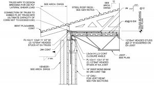
As all structural designers know, one of the most critical items for an effective design is the load path. Load path cannot be stressed enough for storm shelter design. The extreme loads from the storm event must be transferred from the roof to the ground in the most efficient way possible. Although the individual element design (roof, wall, foundation) may be straightforward, the connections are typically the elements that present the most trouble in completing the load path. Figure 3 shows a non-shelter roof structure attaching to the storm shelter cap at a wall bearing condition. The further discussion below references specific items in Figure 3.
Multiple structural systems can be used for storm shelter design. Wall systems typically consist of concrete or concrete masonry unit (CMU) construction. Roof systems typically have a solid concrete cap or concrete topping to meet the wind-borne debris requirements of ICC 500. Still, the supporting structure can range from metal deck on steel beams or joists, precast concrete hollow core, or precast concrete beams. The National Wind Institute at Texas Tech University (https://bit.ly/390w5Wa) has produced significant testing data on the different roof and wall assemblies related to wind-borne debris.
The roof systems should be designed for both the downward gravity load and the uplift loads associated with the increased wind speed. The designer should expect conditions where the uplift forces control the design. When using beams/joists to support the roof system, the designer should provide a way for the slab to positively attach to the supporting beams for uplift forces, and the beams/joists should be designed for negative bending. In Figure 3, please note the headed studs attached to the joist that positively attach the deck/slab system to the joists. Due to the extreme loading, the joist was given an increased seat depth to handle shear loads, and uplift forces were provided to the joist manufacturer to incorporate into the design.
The connection of the roof system to the wall system can be challenging, depending on the thickness of the wall system. As discussed previously, the designer should expect uplift to control the design. In this case, the roof-to-wall connection should be designed to carry these loads. In referencing Figure 3, there are two mechanisms to transfer the uplift forces to the wall: the attachment of the joist seat to the embed plate and the L-shaped reinforcement bars that attach the concrete topping slab to the wall system. One of the primary failure mechanisms for this type of connection is at the bottom or top of the bond beam, so the designer should pay close attention to lap lengths for development of the reinforcement. The use of hooked bars can aid in developing the bars in more restrictive conditions.
The wall systems used for storm shelter design should be designed for both in-plane and out-of-plane wind loads. Particular attention should be paid to jamb and header reinforcement around openings. In addition, the designer should coordinate anchorages of door and window assemblies with the wall design. Typically, CMU is fully grouted to help with wind-borne debris requirements and add weight to the structure for foundation design purposes.
A geotechnical engineer typically dictates foundation systems for storm shelters based on a subsurface exploration of the specific project site. Regardless of the system, foundations are typically controlled by uplift for storm shelters. Similar to the other connection interfaces, the attachment of the wall system to the foundation is critical to the shelter’s performance.
Referring to Figure 3, please note the light gage trusses shown for the non-shelter roof support. For this particular project, the rest of the building had a gabled roof carried over the top of the shelter. This condition falls under ICC 500 Section 304.9, where a host-building element was connected to the shelter. For these types of conditions, the code requires that the shelter is designed to carry the loads associated with the ultimate capacity of the connection in combination with the prescribed shelter loads. Any delegated design must be aware of this requirement, as over-design of these connection elements can impact the performance of the storm shelter.
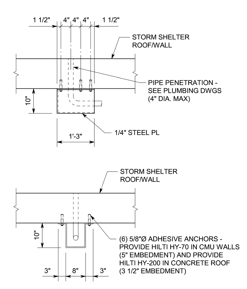
Finally, penetrations larger than a specific size (reference ICC 500 Section 309.1 in 2014 Edition, and Section 306.6 in 2020 Edition) must be protected. This protection is typically accomplished using a steel baffle, a 4-sided box on the interior of the shelter that would stop any wind-borne debris from traveling into the shelter during a storm event. This arrangement requires that most utilities coming into the shelter have a 90-degree turn upon entering the shelter. Please reference Figure 4 for a representative baffle detail.
Moving Towards Construction
In addition to construction documents for the storm shelter, design professionals also need to put together a Quality Assurance Plan. This plan ensures that the contractor knows the storm shelter requirements and critical elements associated with the design.
Typically, the storm shelter design must also be peer-reviewed for the disciplines involved (typically architectural, structural, mechanical, electrical, and fire protection). The peer reviewers must be independent and employed by the owner or the owner’s agent. Peer review reports must be submitted to the authority having jurisdiction (AHJ) as part of the construction permitting process.
Finally, according to the IBC, special inspections are required. It is recommended that shelter elements be considered for special inspections for wind resistance according to the IBC. According to the typical standard of care, structural observations are also recommended, where special attention should be paid to the critical shelter elements and connections.
Finally, communication with the contractor is critical for a successful storm shelter project. The design team should communicate the important elements associated with the shelter, answer questions that arise in the field, and offer “lessons learned” based on previous experience. Some common issues that arise in the field include:
- Additional baffles having to be installed for electrical conduit penetrations because the electrical subcontractor was unaware of the maximum penetration size and drilled an oversized hole in the wall.
- Connections of host building elements to the shelter having to be removed and re-installed because the installer was not aware of the requirements of ICC 500 and provided a connection that was excessive. This connection would lead to additional force being transmitted to the shelter during a storm event and can compromise the design.
- Improper lap lengths used for connections of roof systems to wall systems and wall systems to foundation systems.
Forward Thinking
As the IBC 2018 Edition continues to be adopted in more and more jurisdictions, design professionals must familiarize themselves with the requirements of ICC 500 and FEMA P-361. Additionally, architects and engineers alike should be educating owners on the importance of storm shelters and the costs associated with them.■