
A Stiff Task to Achieve Better Performance and Cost Savings
Wood-framed structural panel shear walls designed using the Force Transfer Around Openings (FTAO) method have become a very popular option for engineers, especially in areas with high lateral force requirements. The need for more affordable housing in metropolitan areas is leading to larger and taller multi-family residential buildings, and these typically wood-framed structures can benefit from the innovative approach behind FTAO design methodology. But do engineers have all the tools they need to accurately determine the stiffness of these walls and the associated lateral force required for their design.
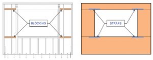
Force-transfer is one of three types of shear walls discussed in the American Wood Council’s Special Design Provisions for Wind and Seismic (SDPWS). The FTAO method considers the strength and stiffness contributed by the wall segments between the window and door openings and the added strength and stiffness contribution from the continuously sheathed wall portions above and below the openings. Whether using the FTAO method or not, builders often opt to provide continuous wood structural panel sheathing across the exterior walls to provide a continuous nail base for cladding materials and eliminate sudden transitions in stucco thicknesses. FTAO shear walls use this continuous sheathing in conjunction with flat steel straps and blocking located at the corners, both above and below, to transfer tension and compression forces around openings (Figure 1).
When the exterior walls of multi-story residential buildings have numerous window penetrations and narrow wall piers between, engineers can be severely challenged to find an adequate amount of shear walls with proper height-to-width aspect ratios capable of resisting code level lateral and overturning demands. FTAO shear walls can provide compliant shear walls using narrow pier lengths to reduce overturning demands (STRUCTURE, January 2018, Hensley).

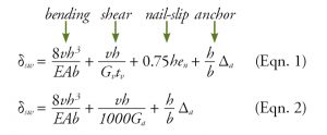
Additionally, this engineering challenge of accommodating numerous window penetrations in exterior wall elevations leads to another trend in multi-family residential construction: using rigid diaphragm analyses in conjunction with engaging long corridor shear walls (Figure 2).
This idea intends to shift much of the shear load away from the weaker, more flexible exterior shear walls inward to the stronger, stiffer interior corridor walls. With a rigid diaphragm model, lateral forces seek out wall elements with larger in-plane stiffnesses, and those typically are longer walls capable of resisting higher forces. In comparison, most engineers use a flexible diaphragm model that simply divides the lateral forces by tributary areas without regard to wall stiffness or strength potential. A flexible diaphragm model is simpler to implement numerically but often is incapable of providing the required resistance associated with conventional wood structural panel shear walls. Therefore, other more costly design options are required.
Calculating Stiffness
The ability to classify a wood diaphragm idealized as either rigid or flexible is found in ASCE 7-16, Minimum Design Loads and Associated Criteria for Buildings and Other Structures, Section 12.3.1, or SDPWS Section 4.2.5. When wood diaphragms are used in conjunction with wood shear walls, the diaphragm’s classification and its proper distribution of forces require the shear wall stiffness to be computed unless the building is only a one- or two-family dwelling. Errors in computing shear wall stiffness lead to errors in the design loads to the walls. Another sometimes appealing alternative is to remove all exterior shear walls in one direction and use only the interior corridor walls in an open-front structure with a rigid diaphragm model; however, numerous code restrictions and significant computational complexity are involved.
The inverse of the computed shear wall deflection (or drift) is used to compute the relative stiffnesses of the various in-plane shear wall lines. The 4-term equation (Equation 1) to compute deflection of segmented shear walls has its origins in published materials since the 1950s and consists of evaluating separate contributions from bending due to chord strains, panel shear deformation, panel nail slip, and wall anchorage slip. The 2001 SDPWS non-linear 4-term equation was replaced in the 2005 SDPWS with a more straightforward linear 3-term equation (Equation 2), with the 4-term equation moved back into the Commentary.
One of the challenges of designing with FTAO walls is accurately determining their stiffness for diaphragm classification and force distribution purposes. Even though currently adopted standards provide no direct guidance on computing FTAO shear wall shears or deflections, the SDPWS does require that these wall types be designed based on a rational analysis. One tool that is now available was developed by APA – The Engineered Wood Association after conducting full-scale experimental research on these wall systems. This research provided, for the first time, a rational method to determine the estimated deflection in FTAO walls that is applicable to symmetric and asymmetric piers and walls with multiple openings supported by full-scale testing (APA Publication M410).
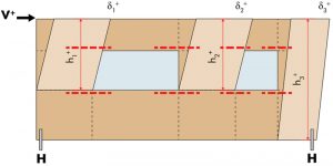
The numeric model assumes the deflection is controlled by full-height piers away from the loaded edge and half-height piers toward the loaded edge (Figure 3), using the conventional shear wall deflection equations. For asymmetrical pier conditions, a deflection is calculated for the load applied in each direction and then averaged to achieve an equivalent deflection and stiffness. Practitioners can consult APA Tech Note T555A, with its companion spreadsheet-based FTAO calculator, to simplify the computations necessary to design these shear wall systems.
Verification by Testing
Recognizing the importance of FTAO shear wall stiffness, several full-scale tests were undertaken between 2019 and 2021 at Cal Poly, San Luis Obispo’s Architectural Engineering Department High Bay Lab, under dry-use conditions. The main objective was to evaluate the appropriateness of APA deflection calculation and methodology with several FTAO configurations. Single opening, symmetric FTAO shear walls with 15⁄32-inch Structural I plywood, Douglas-fir framing (moisture content less than 19%, not kiln dried), 10-penny common nailing, and Simpson Strong-Tie steel strapping and hold-downs were utilized. Other variables such as sensitivity to construction tolerances, imperfections, and conventional wall heights (9-12 feet) were included in the testing. Testing is still ongoing, and dissemination of the results will be provided at some point.

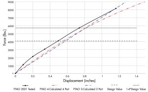
The FTAO walls were designed, built, and tested under faculty supervision by undergraduate and graduate students to supplement their wood design laboratory course, providing a hands-on experience enabling a better understanding of the workings, performance, and constructability issues associated with these wall types (Figure 4). A backbone curve was established from cyclic testing using a hydraulic actuator to apply the lateral force to the wall. As shown in Figure 5, the experimental displacement of this FTAO wall tracked well with the APA calculated deflections using the 4-part equation. It showed that the wall was slightly stiffer than predicted by both the 4-part and 3-part deflection equations.
Design Implications
When developing empirical-based design equations from experimental data, researchers and engineers often tend towards the conservative side when data points are somewhat scattered. However, a conservative (over) estimation of deflection results in an unconservative underestimation of distributed force to that element. Similarly, inaccuracies in shear wall stiffness estimations can also occur due to using the 3-term equation instead of the 4-term equation, ignoring cladding or plaster wall finishes, effects of lumber shrinkage, and construction issues. An additional issue is that the segmented shear wall deflection equations were validated with monotonic loading data. In contrast, the FTAO shear wall deflection computation method is validated with cyclic loading data. How concerned should an engineer be regarding the accuracy of computing wood shear wall stiffnesses in rigid diaphragm systems?
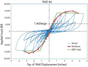
When evaluating these concerns, an important factor to consider is the benefits of non-linear behavior and positive post-yield stiffness of the shear wall systems. The non-linear “softening” of shear wall stiffness seen in Figure 6 will mitigate errors in the engineer’s estimation of shear wall stiffness. For example, consider several shear walls collectively resisting the story shear below a rigid diaphragm. If one wall has more real stiffness than was estimated in the rigid diaphragm model, it will initially attract more load than considered initially. However, this additional wall load may cause the wall to soften to the point that it is less rigid than initially expected and thus redistribute a portion of the load back to the other shear walls. This redistribution of loads associated with non-linear wall behavior below a rigid diaphragm is an excellent asset in the inherent ability of these systems to help resist overloads.
But this reliance on a wall to soften and redirect loads to stiffer elements is only appropriate if there is adequate positive post-yield stiffness for the wall. In other words, once the wall has reached its design capacity and is softening, does it still continue to require more load to get more deflection? This characteristic is closely related to ductility, and wood-framed wood structural panel shear walls obtain significant ductility from the wood-to-wood nailing. As evident in Figure 6, despite the softening of the shear wall, which would allow overloads to be redirected through a rigid diaphragm, the wall continues to have the ability to carry more loads without a sudden loss in strength or stiffness.
Conclusion
In conclusion, wood-framed wood structural panel FTAO shear walls used in conjunction with rigid diaphragms and interior individual full-height wall segments are a popular system that depends upon the proper computation of stiffnesses and strengths. Recent testing and published guidance have given engineers tools to more easily adopt this system into their projects. While it is still important to properly estimate shear wall stiffnesses in a rigid diaphragm model, inadvertent errors in this estimation can be partially mitigated by the non-linearity and ductility of the complete system. Better performance and cost savings can be achieved with a solid understanding of FTAO shear walls.■
References
APA, Research Report 154: Structural Panel Shear Walls, APA – The Engineered Wood Society, Tacoma, WA, Revised July 1999.
APA, Evaluation of Force-Transfer Around Openings – Experimental and Analytical Studies (Form No. M410), APA – The Engineered Wood Society, Tacoma, WA, 2011.
APA, Design for Force Transfer Around Openings – Technical Note No. T555A, APA – The Engineered Wood Society, Tacoma, WA, December 2020.
ASCE 7, Minimum Design Loads and Associated Criteria for Buildings and Other Structures, American Society of Civil Engineers, Reston, VA, 2016.
AWC, Special Design Provisions for Wind and Seismic (SDPWS), American Wood Council, Leesburg, VA, 2015.
Hensley, Jared S., Wood Framed Shear Walls – Utilizing Force Transfer Around Openings, STRUCTURE, National Council of Structural Engineering Associations, Chicago, IL, January 2018.