
Effect of Large Diameter Horizontal Holes
Structural glued laminated timber (glulam) beams are highly engineered components manufactured from specially selected and positioned lumber laminations of varying strength and stiffness. As most glulam beams are designed for and used in applications where they are highly stressed under design loads, drilling or notching of glulam should be avoided and never done without a thorough understanding of the effects on the structural integrity of a member. This is specifically addressed in Section R502.8.2 of the 2021 International Residential Code (IRC) as follows (the same wording also appears in Section R802.7.2 of the 2021 IRC):
R502.8.2 Engineered wood products. Cuts, notches, and holes bored in trusses, structural composite lumber, structural glue-laminated members, cross-laminated timber members, or I-joists are prohibited except where permitted by the manufacturer’s recommendations or where the effects of such alterations are specifically considered in the design of the member by a registered design professional.
APA Technical Note, Field Notching and Drilling of Glued Laminated Timber Beams, Form S560, provides guidance for notching and drilling on glulam when the end notching and drilling of horizontal through-thickness holes cannot be avoided. For the latter, the guidelines are intended to prescribe the size, number, and location of holes to alleviate the reduction in the structural capacities of the glulam. Those prescriptive requirements are helpful for contractors and builders to minimize the need to re-engineer the glulam structural members due to some small horizontal holes.
However, it is not unusual in the structural design phase or in the field that some horizontal holes exceeding the guidance provided in S560 may become a necessity. This document is intended to provide an analytical tool for those conditions through engineering equations and supplemental hole placement requirements. It should be noted that this document is not intended to supersede the recommendations provided by the manufacturer of the glulam used in the specific construction project.
Limitations
a) The analytical equations provided in this document are limited to horizontal round holes. Rectangular holes are outside the scope of this document.
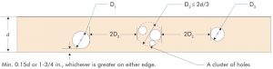
b) The diameter of any holes shall not exceed 2d/3, where d is the glulam depth with d ≤ 24 inches. When d > 24 inches, the maximum hole diameter (D) shall be limited to 16 inches.
c) The hole placement requirements specified in Section 6 of this document are integral to the analytical equations and must be satisfied to maintain the validity of Equations 1 through 3.
d) Equations 1 through 3 apply to simple-span or multiple-span members that carry uniform and/or concentrated loads.
e) The glulam shall meet all requirements of ANSI A190.1, Standard for Wood Products – Structural Glued Laminated Timber, and ANSI 117, Standard Specification for Structural Glued Laminated Timber of Softwood Species, or shall be recognized in a code evaluation report or an APA Product Report®.
Effect of Horizontal Holes on the Bending Capacity
The bending capacity of a glulam member with horizontal holes can be estimated at each hole location using Equation 1. The bending capacity shall meet or exceed the applied moment at each hole location.

Effect of Horizontal Holes on the Bending Stiffness
The bending stiffness of a glulam member with horizontal holes can be estimated using Equation 2. When there are multiple holes in the member, the diameter of the largest hole should be used in Equation 2. The bending stiffness of the glulam member with holes shall satisfy the deflection limit specified in the building code.

Effect of Horizontal Holes on the Shear Capacity
The shear capacity of a glulam member with horizontal holes can be estimated at each hole location using Equation 3. The shear capacity shall meet or exceed the applied shear at each hole location.

Hole Placement Requirements
For the application of Equations 1 through 3, the following restrictions apply:
a) Holes shall be round and neatly cut with a hole saw or a router and template. Holes cut by other means, such as a reciprocating saw, are prohibited.
b) The number of holes in a given span shall be limited to three or less if the diameters of those holes are all greater than d/3. Otherwise, the maximum number of holes in a given span shall not be more than eight, provided that the other requirements of this section are all met.
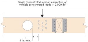
c) A cluster of small holes may be analyzed as a single round hole that circumscribes the cluster and meets all other requirements prescribed in this section, as shown in Figure 1.
d) Holes shall not be cut in cantilevers.
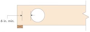
e) The minimum distance along the length of the member between the face of a support and the edge of a hole shall be 6 inches, as shown in Figure 2.
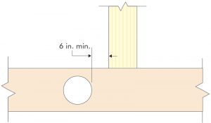
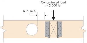
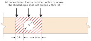
f) At concentrated loads, the minimum distance along the length of the member between the nearest edge of a hole and the face of a top-load object (e.g., column above), as shown in Figure 3, or the edge of a side-load object (e.g., face of the glulam member, or hanger), as shown in Figure 4, and multiple concentrated loads, as shown in Figure 5, shall be 6 inches except for a single concentrated load (Figure 4) or a summation of multiple concentrated loads (Figure 5) that are 2,000 lbf or less. All concentrated loads combined within or above the shaded area shown in Figure 6 shall not exceed 2,000 lbf. The concentrated loads shall not result in a compressive stress that exceeds the allowable edgewise compressive stress perpendicular to grain of the glulam member.
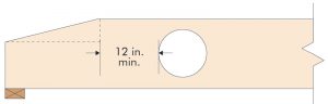
g) For taper or notch cuts at the end of the member, the minimum distance along the length of the member from the end of the taper or notch cut to the nearest edge of a hole shall be 12 inches, as shown in Figure 7.
h) For adjacent holes, the clear distance between holes shall be two hole diameters or larger based on the diameter of the larger hole, as shown in Figure 1. The clear distance shall be measured along the member length, as opposed to diagonally across the member depth if holes are staggered.
i) The hole diameter shall not exceed 2d/3, and the clear distance between the edge of the hole and either edge of the beam shall be at least 0.15d or 1¾ inches, whichever is greater, as shown in Figure 1.■
This article was previously published in APA Technical Note, Form V700, February 2019. It is reprinted with permission.
References
APA – The Engineered Wood Association. 2020. APA Technical Note: Field Notching and Drilling of Glued Laminated Timber Beams. Form S560. Tacoma, WA.
APA – The Engineered Wood Association. 2020. American National Standard Specification for Structural Glued Laminated Timber of Softwood Species. ANSI 117. Tacoma, WA.
APA – The Engineered Wood Association. 2022. American National Standard for Wood Products – Structural Glued Laminated Timber. ANSI A190.1. Tacoma, WA.
International Code Council. 2021. International Residential Code. Country Club Hills, IL.