
Ductility is Critical
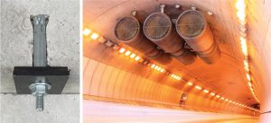
Undercut anchors are the ultimate post-installed anchor category as their load transfer mechanism is bearing, similar to that of headed studs cast into concrete. Tensile loads are transferred into the concrete employing an expansion sleeve driven over a cone into a cavity formed at the back of the drill hole. This mechanical interlock prevents the anchor from pulling out and results in high load capacities and small displacements. Undercut anchors typically show low sensitivity to extreme conditions like large crack widths. If they are made of steel with sufficient material ductility, undercut anchors show a high resistance against cyclic loading. When designed properly and with sufficient embedment depth, undercut anchors have high strength, stiffness, and ductility levels. The design of undercut anchors can also qualify them for ductile connections in seismic design. Their general robustness makes undercut anchors the preferred choice for critical connections where high load demands are to be transferred into the concrete safely (Figure 1).
The Undercut Anchor System
Undercut anchors outperform other post-installed anchor types in several ways. High-performing undercut anchors do not fail in pullout failure mode because the load is transferred deep into the concrete by their solid bearing at the end of the anchor. The anchor load capacity is controlled by the concrete breakout capacity or the steel capacity of the rod, depending on the embedment depth and steel grade chosen. For this reason, undercut anchors are very stiff and develop small displacements when loaded in service. Their ultimate load capacity is very high, and their unique design facilitates the yielding of the rod along its entire length, resulting in a pronounced ductile behavior and deformation capacity.
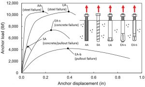
In Figure 2, load-displacement plots give the typical behavior of Adhesive Anchors (AA), Screw Anchors (SA), Undercut Anchors (UA), Expansion Anchors, sleeve type (EA-s), and Expansion Anchors, bolt type (EA-b). As can be seen, the stiffest and strongest anchors are the adhesive and undercut; however, the undercut anchor has greater ductility in tension than the expansion anchor due to the rod of the undercut being debonded over its length (greater stretch length).
Undercut anchors are used for critical applications where their superior performance outweighs the higher relative costs when compared to other anchor types like expansion anchors. Specifiers, design professionals, and installers should thoroughly understand the complete undercut anchor system and its benefits. The correct selection of anchors and accessories is vital for proper and easy installation. The complete system typically consists of:
- Undercut anchor
- Drill bit for the primary hole
- Undercut bit for creating the undercut
- Setting tool to set the anchor
- Hammer drill for drilling, powered undercutting, and setting
- Optional dust extractor to vacuum the dust created during drilling
Installation
Undercut anchors are not an everyday construction product, but they can provide specialized solutions. Undercut anchors do not require specialized installer training. However, since they are utilized less frequently than typical expansion anchors, the installer should be familiar with their installation (Figure 3).
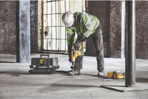
No power tool other than a hammer drill is required for the installation. The primary hole is drilled straight into the concrete member using a drill bit that meets the American National Standards Institute (ANSI) requirements. The hole has to be drilled to the required depth. Stop drill bits are also available, which control specific dimensions meeting the anchor requirements and can be a foolproof choice.
Undercut anchors are insensitive to uncleaned holes; however, to facilitate the following undercutting and installation procedure, the hole must be free of drill dust which is removed using a vacuum or compressed air for downward and horizontal installations. Using hollow bits in conjunction with a high-efficiency particulate air (HEPA) vacuum is the easiest way to meet the Occupational Safety and Health Administration’s (OSHA) Table 1 requirements for reduced dust exposure. Hollow bits remove the drill dust directly via a vacuum connected to the bit during drilling. Then, the undercut is customarily formed utilizing a special undercut bit, which may be hollow to suction drill dust, easing the undercutting operation and making an additional cleaning step unnecessary.
Finally, the anchor is inserted in the hole, and the expansion sleeve is driven over its conical end with a hammer drill. The sleeve allows the internal anchor rod to stretch freely when loaded in tension while it supports and prevents the rod from buckling when loaded in compression. This is a critical requirement for ductile design, as discussed later in this article.
Selection
There are various versions of undercut anchors available and in different materials. Selecting the optimum version requires careful consideration by the planner. The design professional defines the anchor diameter and embedment depth to meet the load demand. Other parameters like minimum thickness and edge distance of the concrete member also influence the selection of the appropriate anchor. The standard version of the anchor is pre-set prior to the installation of the fixture. There is also a thru-bolt version where the sleeve protrudes through the fixture for increased shear load capacities.
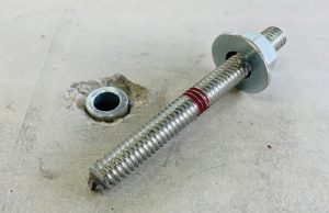
Selecting steel grades that are ductile and develop sufficient resistance against cyclic loading for high seismic load capacities is critical (Figure 4).
Ductile steel is also critical in applications where the anchor may be subject to fatigue loading, like the anchorage of sign structures or rotating equipment. If the anchor is exposed to a corrosive environment during construction or service life, stainless steel anchors should be strongly considered. Unlike adhesive anchors, undercut anchors are not affected by weather conditions like wetness or extreme temperatures, neither during installation nor in service, and can be immediately loaded after installation.
On top of these technical requirements, there might be specific project and/or legal requirements for parts being made in the United States. For example, this is often the case for military and government-funded infrastructure projects.
Product Qualification
The importance of product qualification for critical connections should not be taken lightly or for granted. Only undercut anchors independently tested and evaluated to recognized standards should be considered for use. For post-installed mechanical concrete anchors, including undercut anchors, ACI 355.2, Qualification of Post-Installed Mechanical Anchors in Concrete, provides testing conditions and assessment criteria to qualify anchors for their intended use. This is the basis for product evaluation reports issued from recognized approval bodies. The International Code Council Evaluation Service (ICC ES) is one such approval body that issues Evaluation Service Reports (e.g., ESR-4810).
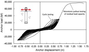
The extensive test program for an ACI 355.2 qualification assesses the behavior and performance of the anchor regarding its reliability, suitability, and serviceability. The outcome is the design data certified in the product evaluation report, which are product-dependent load capacities. Most tests are static pullout tests on installed anchors under various conditions, e.g., uncracked and cracked concrete and low strength and high strength concrete. More sophisticated tests include cyclic tests assessing the anchor performance under seismic conditions. The anchor is loaded by a recurring and repeating standard seismic protocol to defined load levels simulating earthquake loading. Figure 5 shows the load-displacement diagram of an example shear test. After completion of all prescribed lateral loading cycles, the anchor must still be able to develop sufficient residual load capacity and show proper behavior to achieve qualification for seismic connections.
Design and Software
Post-installed concrete anchors are regulated in the design code ACI 318, Building Code Requirements for Structural Concrete and Commentary, and ACI 349, Code Requirements for Nuclear Safety-Related Concrete Structures, for structural concrete. The resistance of the anchor connection is calculated as the minimum of various failure modes, namely concrete breakout and steel rupture. High-performing undercut anchors do not fail in pullout failure mode, in which case this mode can be neglected. The design strength capacities of the anchors are calculated in tension and shear, which are checked against the applied demand loads derived from static and seismic analysis. Specialized design software (for example, DDA™ from DEWALT: www.DEWALTdesignassist.com) can quickly model and accurately carry out the complex anchor design.
There are several options for the seismic design of anchors in tension. Generally, the most overall economic design is the ductile design consideration. The ductile design option does not require the increase of the earthquake design load by the overstrength factor (W0), which is often as high as 2.5 for the elastic design option. However, additional provisions must be met for a ductile anchor design.
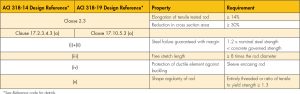
Here is a breakdown of the ductility provisions within ACI 318, as shown in the Table.
- When tested in tensile tests, the rod as the load transferring steel element must show minimum elongation and reduction on the cross-sectional area. If the steel can be classified as ductile, beneficial strength reduction factors may be used to calculate the design strength of the anchor.
- The nominal steel strength of the anchor has to be smaller than any concrete-governed strength by a margin of 20% to safely preclude brittle concrete failure. In the case of undercut anchors, concrete-governed strength is the nominal strength considering concrete breakout and, only if applicable, pullout strength.
- The rod must provide a free stretch length of 8 times the rod diameter or more to ensure sufficient absolute deformation can be generated.
- The rod must be protected by a sleeve against buckling occurring when the rod is loaded in compression during cyclic load reversals.
- The rod must be either entirely threaded, or the tensile strength must be 30% higher than the yield strength to ensure that yielding occurs within the stretch length before failure in the threads.
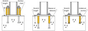
ACI 318 illustrates two possible details to facilitate sufficient free stretch length, both of which require special measures and additional anchor lengths. Undercut anchors, however, can enable an economical solution for ductility with no extra effort (Figure 6).
Conclusion
The robustness of heavy-duty undercut anchors makes them an ideal solution for structural applications in transportation, energy, industrial, port, and waterway projects. Undercut anchors can meet the challenging demands of extreme design situations with a high level of safety by providing high levels of strength, stiffness, and ductility. Ductility plays a vital role in various aspects of both product qualification and design. Anchors made of ductile steel resist high loads during simulated seismic tests according to the ACI 355.2 standard to qualify for high seismic design strengths documented in Evaluation Service Reports (ESRs).
In addition, undercut anchors meeting stringent geometric and material requirements can qualify for the additional and highly beneficial ductile design option according to the ACI 318 design code. Specialized design software is available to support the structural engineer in conducting these complex anchor design ductility checks and associated calculations.■