
Fastener Schedules, Overhang Limits, and Uplift Connectors
Component and cladding (C&C) wind pressures calculated using ASCE 7-16, Minimum Design Loads and Associated Criteria for Buildings and Other Structures, increased over ASCE 7-10 C&C wind loads. In addition to larger corner and edge areas on roofs, ASCE 7-16 also includes increased roof pressures for low-rise (simplified) buildings with height (h) less than 60 feet and buildings taller than 60 feet with hip, gable, or flat roofs.
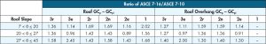
In the case of a flat roof on a low-rise building using the simplified method, pressures for corner, edge, and interior areas increased from 13 percent to 81 percent, with an average increase of over 40 percent. For other roof slopes, Table 1 shows a comparison of C&C loads for ASCE 7-16 versus ASCE 7-10.
Between the increase of C&C roof areas assigned to corner and edge regions and the increase in C&C roof pressures, nail schedules for wood structural panels (WSP) changed, with nail spacing cut in half in some cases. For similar reasons, in the International Residential Code® (IRC), overhang detailing includes limits on gable endwall WSP cantilevers. Uplift connectors for gable endwall rake overhang outlookers to the endwall require engineering or can be sized based on Wood Frame Construction Manual (WFCM) prescriptive tables to account for increased C&C loads at roof edges.
Uplift connectors at rafter or truss bearings are based on main wind force resisting system (MWFRS) loads. MWFRS loads did not change in ASCE 7-16. The International Building Code® (IBC), IRC, and WFCM have uplift connection load tables that can be used to size roof-to-wall uplift connections.
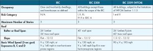
The WFCM is a referenced alternative approach to the IRC based on IRC Section R301.1.1. Also, note that, for risk category I or II buildings, IBC Section 2309 permits the use of the WFCM and its load assumptions for buildings within the WFCM scoping limitations. Table 2 shows scoping provisions for the IRC and IBC Sections 2308 and 2309 relative to the roof and wind loads for light-frame wood construction.
Roof Sheathing Fastener Schedule Changes
In the 2021 IBC and 2021 IRC, nailing patterns for wood structural panel roof systems have been updated. Reduced nail spacing is based on wind loads from ASCE 7-16 and is consistent with roof sheathing nailing requirements in the 2018 WFCM.
A previous article (STRUCTURE, Changes to the 2018 WFCM, June 2018) provided background information on increases to component and cladding wind loads in ASCE 7-16 which led to these changes (Table 1). Updates to the prescriptive fastener tables in the 2021 IBC and 2021 IRC now provide consistency with the building codes and their referenced standards.
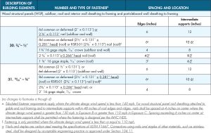
IBC Table 2304.10.2 and IRC Table 602.3(1) contain similar prescriptive fastener schedules for wood construction. Only changes to IBC Table 2304.10.2 Items 30 and 31 are shown here (Table 3). Similar changes were made to IRC Table 602.3(1).
Wind uplift nailing requirements for common species of roof framing with specific gravities (G) of 0.42, based on spruce-pine-fir (SPF), are the basis of the proposed nail spacing requirements in IBC Table 2304.10.2. This is to meet the wind uplift loading requirements of ASCE 7 without being overly complex in the specification of WSP roof sheathing nailing. The basic roof sheathing nailing schedule is 6 inches on-center at panel edges, and 6 inches on-center at intermediate supports in the field of the panel.
This nailing schedule applies to ⅜-inch through ¾-inch wood structural panels fastened to framing with 8d common or deformed nails or roof sheathing ring shank (RSRS-01) nails with dimensions as shown in IBC Table 2304.10.2. Head diameters are specified and important due to new provisions in the 2018 National Design Specification® (NDS®) for Wood Construction accounting for head pull-through in calculating nail capacities.
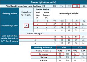
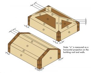
As shown in Table 4 for the common case of roof framing spaced at 24 inches on-center, nailing at intermediate supports in the interior portions of the roof is 6 inches on-center for wind speeds within the scope of IBC Section 2308 Conventional Light-frame Construction. The 6 inches on-center spacing is also appropriate for edge zones (Figure 1) except where ultimate wind speeds equal or exceed 130 mph in Exposure B and 110 mph in Exposure C, where 4 inches on-center nailing is required. These special cases are addressed by the addition of IBC Table 2304.10.2 footnote “e” (Table 3).
To update the alternative fastening to uplift loading requirements of ASCE 7 without being overly complex in the specification of wood structural panel roof sheathing attachment schedules, IBC Table 2304.10.2 footnote “f” was also added. The reference calculation leading to the use of 3 inches on-center spacing at all locations is based on a 0.113-inch diameter nail (e.g., 6d common) shank withdrawal from wood framing with specific gravity equal to 0.42 (SPF) and pre-calculated wind uplift loads in WFCM Table 3.10. The use of a single 3-inch spacing at all supports was extended to staples based on the assumption that the ASCE 7 load increase would similarly require reduced spacing. This assumption was applied to staples because a withdrawal value is not available for staples in the NDS.
Stainless steel nails have lower withdrawal strength when compared to carbon steel wire nails of the same diameter due to the reduced surface friction of stainless steel. The differences in withdrawal strength vary with the specific gravity of wood (STRUCTURE, Changes to the 2018 NDS, February 2018). When stainless steel nails are specified as an alternative to reference smooth shank carbon steel wire (bright or galvanized) nails in wood construction, these differences in nail withdrawal strengths must be considered. For example, where smooth shank stainless steel nails are used for roof sheathing attachments, more nails or nails of greater length or diameter may be required to provide equivalent withdrawal strength performance for wind uplift. IBC Table 2304.10.2 footnote “g” was added to address this issue.
Gable Endwall Overhang Detailing
While gable endwall overhangs can be engineered per the NDS, the WFCM contains helpful tables and details for common rake overhang conditions. Per WFCM Section 2.1.3.4(c), rake overhang length is not to exceed the lesser of one‑half of the outlooker length or 2 feet. WFCM Section 2.2.6.8 indicates that rake overhang outlookers shall be connected to the gable endwall in accordance with the wind uplift loads specified in Figure 2.
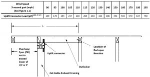
Tabulated outlooker uplift connection loads in Figure 2 are based on Zone 3 C&C roof wind loads and assume a building located in Exposure B with a mean roof height (MRH) of 33 feet. For buildings located in Exposure B with mean roof heights less than 33 feet or Exposures C or D, tabulated values are increased with appropriate adjustments. Tabulated outlooker uplift connection loads are based on 2-foot overhangs, 2×4 gable endwall framing, and uplift connectors location on the inside face of 2×4 gable endwall framing. For overhangs less than 2 feet, tabulated uplift connector load values can be decreased linearly. For overhangs located in Zone 2 per Figure 1, tabulated uplift connector loads are permitted to be multiplied by 0.74. Tabulated outlooker uplift connection loads are calculated assuming a roof pitch range greater than 1.5:12 and less than or equal to 6:12. For roof pitches greater than 6:12, tabulated values are permitted to be multiplied by 0.85. Tabulated uplift connector loads are specified in pounds per linear foot along the gable endwall. Tabulated uplift connector loads are adjusted based on the connector spacing to determine connection requirements (pounds).
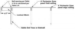
In IRC Section R803.2.3, WSP roof sheathing cantilevers are limited to no more than 9 inches beyond the gable endwall unless supported by gable overhang framing. This is consistent with WFCM prescriptive limits for rake overhangs. Per WFCM Sections 3.1.3.4(c) and 3.5.1.1.3, rake overhangs must be continuous 2×4 members, and the overhang length is not to exceed the lesser of one‑half of the outlooker length or 2 feet (Figure 2). An exception permits rake overhangs using lookout blocks of no more than 9 inches (Figure 3).
WFCM Table 3.4C provides rake overhang outlooker uplift connection loads similar to those shown in Figure 2. However, WFCM Table 3.4C shows both Exposure B and Exposure C values and is expanded to show values based on overhang span and outlooker spacing.
Rafter/Truss Overhang Limits
There is no specific limit for rafter/truss overhangs in the IBC. Per IBC Section 2308.8.2, structural elements not described in IBC Section 2308 require design.
IRC Section R802.7.1.1 indicates that notches on cantilevered portions of rafters are permitted provided the dimension of the remaining portion of the rafter is not less than 3½ inches and the length of the cantilever does not exceed 24 inches per IRC Figure R802.7.1.1.
WFCM Sections 2.5.1.1.2 and 3.5.1.1.2 specify that rafter overhangs shall not exceed the lesser of one-third of the rafter span or 2 feet.
Rafter/Truss Uplift Connections
Uplift connectors at rafter or truss bearings are based on main wind force resisting system (MWFRS) loads. The IBC, IRC, and WFCM have uplift connection load tables that can be used to size roof-to-wall uplift connections.
IBC Section 2308.7.5 requires rafter and truss ties to the wall below with the resultant uplift loads transferred to the foundation using a continuous load path. The rafter or truss-to-wall connection has to comply with Tables 2304.10.2 and 2308.7.5. The former includes prescriptive rafter or roof truss to top plate uplift fastener schedules, as shown in Table 5.
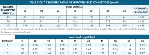
IBC Table 2308.7.5 (Table 6) includes tabulated uplift connection values for uplift connectors and overhangs. The uplift connection requirements are based on framing spacing of 24 inches on-center. Smaller spacings can be adjusted linearly. The uplift connection requirements include an allowance for 10 pounds of dead load.
For the effects of overhangs, the magnitude of the loads is increased by adding the overhang loads found in IBC Table 2308.7.5. The overhang loads are also based on framing spaced 24 inches on-center. The overhang loads given are multiplied by the overhang projection and added to the roof uplift value in the table.
The uplift connection requirements are based on wind loading on end zones as defined in ASCE 7 Figure 28.5-1. Loads for connections located a distance of 20 percent of the least horizontal dimension of the building from the corner of the building are permitted to be reduced by multiplying the table connection value by 0.7 and multiplying the overhang load by 0.8.
Interpolation is permitted for intermediate values of Vasd and roof spans. The rated capacity of approved tie-down devices is permitted to include up to a 60-percent increase for wind effects where allowed by material specifications such as the NDS.
IRC Table R802.11 contains ASD wind uplift loads based on ultimate design wind speeds (VULT) of 110 – 140 mph for both Exposure B and C. Rafter or truss spacings range from 12 to 24 inches on-center, roof spans range from 12 to 48 feet, and roof pitches are shown for less than 5:12 and for 5:12 and greater.
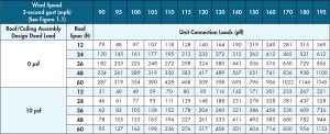
WFCM Table 2.2A includes wind uplift connection loads, as shown in Table 7. Tabulated uplift loads equal total uplift minus 0.6 of the roof/ceiling assembly design dead load. Tabulated unit uplift connection loads shall be permitted to be multiplied by 0.75 for framing not located within 6 feet of corners for buildings less than 30 feet in width (W) or W/5 for buildings greater than 30 feet in width.
Tabulated uplift loads are based on MWFRS wind loads and assume a building located in Exposure B with an MRH of 33 feet. For buildings located in Exposures B with MRHs less than 33 feet, or in Exposures C or D, tabulated values for 0 psf roof dead load can be adjusted then reduced by the appropriate design dead load.
Tabulated uplift connector loads are specified in pounds per linear foot along the wall. Tabulated uplift connector loads are adjusted based on the connector spacing to determine connection requirements (pounds).
Conclusion
C&C wind pressures calculated using ASCE 7-16 increased over ASCE 7-10 C&C wind loads. Between the increase of C&C roof areas assigned to corner and edge regions and the increase in C&C roof pressures, nail spacings for wood structural panels (WSP) are significantly reduced in some cases. For similar reasons, in the IRC, overhang detailing includes 9-inch limits on gable endwall WSP cantilevers. Uplift connectors for gable endwall rake overhang outlookers to the endwall require engineering or can be sized based on WFCM prescriptive tables to account for increased C&C loads at roof edges.
Uplift connectors at rafter or truss bearings are based on MWFRS loads. MWFRS loads did not change in ASCE 7-16. The IBC, IRC, and WFCM have uplift connection load tables that can be used to size roof-to-wall uplift connections.■