
Many engineers consider rectangular structures with light gauge metal deck diaphragms unstable if they are laterally supported on only three sides. Given the standard assumption that light gauge metal deck diaphragms are completely flexible, this type of structure, often referred to as a 3-sided box, would be unstable. While this assumption is often useful for diaphragm design, it is not strictly true. Light gauge metal deck diaphragms have stiffness, and 3-sided box structures are stable when designed properly. A design method for this type of diaphragm was introduced in the Steel Deck Institute’s Diaphragm Design Manual (DDM) 2nd Edition in 1995. Since then, many single-story structures have been designed using this method, demonstrating its validity. Additional information can be found in the current DDM 4th Edition in Section 10, Example 7.
It is not uncommon for tilt-up and precast warehouses in low seismic regions (SDC A & B) to be designed with a rectangular diaphragm laterally supported on three sides when an expansion is added to an existing building or when an expansion joint is required due to the building length. The following explanation and design example focuses on wind loads on a rectangular building with shear walls on three sides and no lateral force resisting system (LFRS) on the fourth. The fourth side is assumed covered, with no wind pressure acting on it.
Windward/Leeward Shear Loads
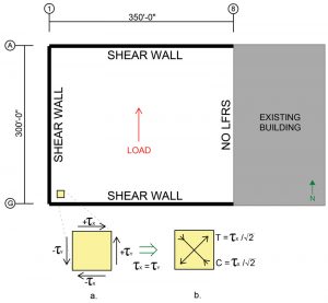
For lateral loads in the north/south direction (Figure 1), parallel to only one shear wall, the shear and moment in the roof can be calculated as if the roof were a fixed-free beam, fixed at the shear wall end and free at the opposite end. The shear wall parallel to the load resists the shear in the north/south direction, while the shear walls perpendicular to the load act as flanges to resist the moment. The LFRS’s perpendicular-to-the-wind load must form a couple to resist the moment to keep the structure in equilibrium and resist twisting and structural collapse. In addition, these shear walls must transmit the lateral load from the roof diaphragm to the foundation to complete the load path and stabilize the structure.
Inherent in this design approach is that the roof behaves as a rigid diaphragm. ASCE 7-16 Section 26.2 permits untopped steel decks to be idealized as rigid for wind design if the span-to-depth ratio is not greater than 2. Yet, Section 12.3 only allows concrete-filled metal deck to be idealized as rigid for seismic design, forcing semi-rigid analysis of the deck. However, relative stiffnesses of the diaphragm and vertical lateral force resisting systems do not affect the total load distribution to any of the vertical LFRS. With restraints on only three sides, the only way for the system to maintain equilibrium is for the loads to be distributed as if it were a standard rigid diaphragm.
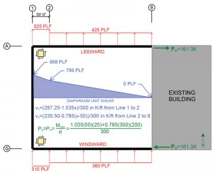
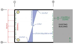
The shear diagram produced by this loading in the north/south direction is intuitive based on standard beam theory. Figure 2 shows the unit shear diagram for the loads given in the figure. The total load that must be resisted by the shear walls perpendicular-to-the-wind load, to maintain equilibrium and resist the torsion on the structure, can be calculated by ensuring the sum of the moments on the structure equals zero. This can be done easily if the point about which the moments are calculated is chosen as corner A-1 or G-1. The total load P in shear walls A and G can be calculated by dividing the moment at A-1 or G-1 by the depth of the roof. Figure 2 shows the calculation of this force where the load, P, at lines A and G must be in opposite directions to maintain equilibrium.
For the load, P, to accumulate in shear walls A and G, the load must be transferred from the diaphragm into the shear walls. It is often assumed that this is an additional shear load in the diaphragm that needs to be combined with the direct shear parallel with the wind load. However, this is not correct. The shear being transferred into the shear walls at lines A and G is the perpendicular component of the direct shear and is not additive. To better understand this, consider the shear on a small square section of the roof diaphragm, as shown in Figure 1a.
For equilibrium to be maintained on this roof section, for both translation and rotation, a force couple must exist on both the left and right and top and bottom of the square. In Figure 1a, the component of the shear stress parallel with the load is represented as τy, and the component of the shear stress perpendicular to the load is represented as τx. It is the τx shear stress that is transferred into the shear walls at A and G.
Admittedly, considering small square sections of a diaphragm with stress couples and transforming that into the loads on a large roof is not intuitive. As evidence that the load transferred to shear walls A and G is a component of the direct shear and not additive, consider the following. First, take into account that the area under the shear diagram in Figure 2 equals P. Second, consider that the unit load transferred into shear walls A and G can be calculated by taking the change in moment in the diaphragm between two adjacent points and dividing that by the depth of the building (δM/δx)/d and that this will exactly equal the shear diagram in Figure 2.
Shear as Tension/Compression Struts
It may also be helpful to consider the shear in the diaphragm from another perspective. Shear, considered a set of perpendicular tension and compression stresses turned 45 degrees from the applied load, as shown in Figure 1b, is equivalent to Figure 1a. Each resists the same amount of shear, and each has equilibrium maintained. There are, however, two advantages of viewing the shear as shown in Figure 1b. Generally, it provides a clear illustration of why shear cracks in concrete form at 45 degrees to the applied load. Specifically, this case provides an easier way to visualize how shear can be transferred into a shear wall perpendicular to the applied load. If the diagonal tension and compression loads are enlarged from the small square of the roof diaphragm into macro-level x-braces throughout the roof, it provides an alternative method for viewing the roof shear, as illustrated in Figure 3.
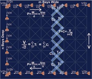
By setting up a model of the example building’s roof diaphragm with an x-brace in each bay, roller supports around the perimeter resisting translation parallel to the shear walls, and a shear load, V, at the free end, statics can be used to show how the shear load is transferred into the shear walls. With n bays vertically and m bays horizontally, it also allows a quick calculation for the load, P, in shear walls A and G. Since the load in each diagonal member is V/(n√2), the horizontal component is V/2n. There are 2m diagonal members framing into each east/west shear wall; therefore, the total load P = 2Vm/2n = Vm/n, which equals the moment at corners A-1 or G-1 divided by the roof depth as discussed above. Readers are encouraged to spend 15-20 minutes setting up a similar diaphragm in their preferred structural modeling software with various loading patterns. The results will demonstrate the structure’s stability, the shear in the diaphragm, and the load transfer to the shear walls.
Sidewall Shear Loads
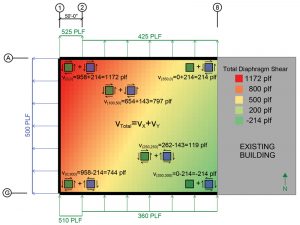
While the windward and leeward wind loads being transferred to shear walls A and G are not additive to the direct shear, there is often additional shear load in this type of 3-sided box structure that does need to be considered. When calculating the Main Wind Force Resisting System forces in the diaphragm of a traditional 4-sided structure, the sidewall wind forces often cancel each other out since they are equal in magnitude but act in opposite directions. However, for the 3-sided box shown in this example with no wall at line 8, there is no opposing sidewall wind force to counteract the sidewall wind at line 1. This sidewall wind pressure produces a shear diagram like a simply supported beam between the two parallel shear walls, as shown in Figure 4.
Combining Shear Loads
The sidewall wind shear must be added to the windward and leeward wall wind shear to calculate the total shear load in the diaphragm at any location. At Line A, the combination of the shear loads is additive, while at line G, the shear loads are in opposing directions. The shear diagrams on small squares of deck shown in Figure 5 can help visualize the shear direction at various locations. The maximum shear occurs at corner A-1 and decreases when moving away from the corner in each direction. This combined shear load is checked against the diaphragm shear capacity to determine the adequacy of the design.
The wind may blow in any direction, so while corner A-1 may have the maximum shear one moment, corner G-1 may have the maximum shear the next. The diaphragm should be designed with this in mind. On large diaphragms, it is common to vary the deck gauge and connection patterns across the roof as the shear forces change.
Chord Forces
The sidewall wind pressure creates bending moment in the roof. This moment can be calculated by assuming the roof as a simply supported beam between shear walls. At the free end of the structure, this moment is generally designed to be resisted only by the members along line 8. The sidewall pressure-producing suction on the wall creates a compression chord force at line 8, which can be calculated as shown in Figure 4.
This force will typically either be resisted by the top chords of the joists along line 8 or by a continuous perimeter angle. If resisted by joist top chords, a tie plate or tie angles must be added between joists to transfer load from one joist to the next.
The tension force created by the moment in the diaphragm at line 1 will not build up in the perimeter angle along the wall as the compression force does in the perimeter angle/joist top chords at line 8. At line 1, the chord force is transferred into the wall panels at each connection. Similarly, the chord force along lines A and G from the windward/leeward loads will not build up in the perimeter angle along those lines but will be transferred to the shear walls with each connection.
Design Considerations
While the ANSI/AWC wood code (Special Design Provisions for Wind and Seismic, SDPWS) places dimensional limits and L/W ratio limits on diaphragms of open-front structures, there are no such dimensional or L/W ratio code requirements on light gauge steel roof deck diaphragms. As a practical matter, it is generally advisable to limit the unit shear in the deck to that which 20-gauge deck can resist. Experience has shown that adding a line of braces or moment frames near the open end of the structure is generally less expensive than leaving that end without an LFRS when 18-gauge deck is required due to the cost of the heavier deck and additional deck connections.
To ensure that all lateral deflection requirements are met, the deflection of the diaphragm must also be checked. As noted in the DDM 4th Edition, a diaphragm with the dimensions shown in this example is controlled by shear deflection; therefore, flexural deflection is ignored. Assuming uniform stress over the depth of the diaphragm, the deflection between any two points can be calculated by the following integration:
where V is the shear, b is the depth of the diaphragm, and G´ is the diaphragm shear stiffness. For a uniformly loaded cantilevered diaphragm with a uniform depth and uniform stiffness, the maximum deflection at the free end can be calculated as
where q is the uniform load and L is the length of the diaphragm. For this example, where the load is not uniform across the entire length of the diaphragm, the deflection at the free end can be found by dividing the area under the unit shear curve shown in Figure 2 by G´. The equation for G´ can be found in the DDM 4th Edition and varies based on the deck type and gage, fastener type, and connection pattern.
Rectangular light gauge metal roof deck diaphragms with LFRS on three sides have been successfully designed and constructed using the design method described above for decades. Efficient and safe designs can be implemented with a proper understanding of the shear in the roof diaphragm and how it is transferred to the shear walls. Understanding this design approach provides engineers with another arrow in their quiver of design techniques and provides another way to meet client needs.■