
Galloping Gertie, Part 1
The collapse of the Tacoma Narrows Bridge is one of the most well-known of all bridge failures as its collapse was caught on film. The film was and still is viewed in many introductory physics classes.
Planning for the bridge started in 1929, just before the Great Depression, when proponents of the bridge, including the Tacoma Chamber of Commerce, pushed for its construction. It was to cross an arm of Puget Sound, the Tacoma Narrows Strait in the State of Washington connecting Tacoma with Gig Harbor.
In 1929, D. B. Steinman proposed a suspension bridge followed in 1931 by a cantilever bridge by the Tacoma City Engineer. In 1932, a local engineer formed the Tacoma Bridge Company that hoped to raise at least $3.5 million to construct a Narrows suspension bridge. The Corps of Engineers approved his plan, but the Reconstruction Finance Administration (RFA) would later propose a cantilever bridge as preferable. In the late 1930s, the Washington State Legislature created the Washington Toll Bridge Authority to finance and operate bridges in the State, including the Tacoma Narrows.
It should be understood that, by this time, New York City had built the Brooklyn Bridge in 1883, the Williamsburg Bridge in 1903, the Manhattan Bridge in 1909, and the George Washington Bridge in 1931. Also, for the record, the Wheeling Bridge by Charles Ellet, Jr. (1849), the Lewiston-Queenston Bridge (1851) by Edward W. Serrell, and the Niagara Clifton Bridge (1899) by Leffert L. Buck had all been destroyed by the action of winds. These failures were well documented in the literature of the day.
Significant changes in suspension bridge design occurred between 1903 and 1909, incorporating the Austrian Josef Melan’s deflection theory. Melan’s main breakthrough was the understanding that the deck and the cables act together to carry vertical loading and that, as the span length increased with greater dead loads, the need for a stiffening truss was reduced greatly. Leon Moisseiff, then working for the City of New York, translated Melan’s work and applied it to the design of the Manhattan Bridge with its 1,590-foot span and 25-foot-deep stiffening truss. Next, O. H. Amman applied it to the design of the George Washington Bridge, when he virtually eliminated all deck trussing, relying on the weight of the cable only for roadway stiffness. The Williamsburg Bridge by Leffert L. Buck, with its 40-foot-deep stiffening truss, was the last major bridge to be built using the elastic method first proposed by William M. Rankine. Finally, on the Golden Gate Bridge, Joseph B. Strauss and Charles Ellis, with Leon Moisseiff, used a stiffening truss of a far lesser depth than the shorter Williamsburg Bridge. Moisseiff also applied it to the Bronx Whitestone Bridge across the East River in New York City, built between 1936 and 1939.
The first design for the Tacoma Narrows Bridge by the Washington Toll Bridge Authority was by Clark Eldridge, an engineer for the state. It was a conventional suspension bridge with a 25-foot-deep stiffening truss on either side of the roadway to resist the strong Narrows winds. He estimated the cost of the bridge at $11,000,000. Its main span was 2,600 feet with side spans of 1,300 feet and a sag of 260 feet. The Director of the Washington State Highway Department took the design to the Public Works Administration (PWA) and, by most accounts, they determined the $11 million was excessive and urged the state to contact Leon Moisseiff and the firm of Moran & Proctor for a cheaper design, which they did. J. J. Madigan, the head of the PWA, later wrote, “In no instance did this Administration nominate or express any preference for any particular individual, group, or firm.” Eldridge later wrote, Moisseiff and Moran and Proctor “associated themselves to secure the commission to design the Tacoma bridge. They went to Washington, called on the Public Works Administration, and informed them that they could design a structure here that could be built for not more than $7,000,000. So, when Mr. Murrow appeared asking for $11,000,000, our estimate, he was told $7,000,000 was all they would approve. They suggested that he confer with Mr. Moisseiff and Moran and Proctor. This he did, ending up employing them to direct a new design.” What really happened is unknown, but Eldridge was likely closer to the truth.
In June 1938, President Roosevelt approved a grant for about $2.8 million and a loan of $3,300,000. After the bids were received, this was increased to a total of $6,400,000. The loan was to be paid back from tolls.
Moisseiff, after reviewing Eldridge’s design, proposed a suspension structure with 1,100-foot side spans, a 2,800-foot main span, and a sag of 232 feet. Its road deck measured 26 feet curb-to-curb. In addition, it had 5-foot sidewalks, the same as Eldridge. He wrote, “To approach the problem from another angle, the stiffening trusses may practically be omitted, and the desired rigidity can be obtained by other means, shortening of side spans and reduction in sag ratio…” and “…To stiffen the bridge vertically as well as transversely, the main span has been increased to 2,800 feet, and the side spans reduced to 1,100 feet.” This resulted in a sag ratio of 1/12.2, flatter than any suspension bridge in the United States. His towers soared 425 feet above the piers and were battered, 50 feet at their bases tapering to 39 feet at their top. He also made them the same height while Eldridge had his at different heights. He designed it with an 8-foot-deep plate girder serving in place of Eldridge’s deep trusses, thus saving a great deal of steel. The cables were spaced 39 feet center-to-center. With its narrow width (roadway 26 feet and two sidewalks of 4 feet 9 inches) and span of 2,800 feet, it resulted in a depth to span length ratio of 1:350. Up to this time, the greatest value of this measure was 1:84. The width of the deck-to-span ratio of 1:72 was also the narrowest of any bridge built to this time. Moisseiff’s design was by far the longest, thinnest, and narrowest suspension bridge ever built and contributed to its sleek appearance. The 2,800-foot suspended span made it the third-longest suspension bridge in the world after the George Washington and the Golden Gate Bridge, both of which Moisseiff was involved in as a consultant.
Moisseiff believed that its stiffness depended on structural weight and proportion and that he “could reduce truss depth without adversely affecting bridge stiffness.” He carried this theory further by postulating that the use of shallower stiffening trusses naturally led to plate girders, which he believed offered “many structural advantages for connections and fabrication” and “presented a simple and good appearance and [were] easy to maintain.” Finally, he believed “that cables had the ability to control and supply stiffness to a suspension bridge. By flattening the catenary of the cables to a modified parabola, he could increase the rigidity of the bridge’s polygon, again reducing the stiffening girder’s depth.”
Lacey Murrow had three engineers review Moisseiff’s design, and they reported, on August 31, 1938, in part, “We have examined the superstructure design as to its general features. Time has not permitted the checking of stresses in the cables and stiffening trusses. In this regard, we have full confidence in Mr. Moisseiff and consider him to be among the highest authorities in suspension bridge design.
It might seem to those who are not experienced in suspension bridge design that the proposed 2,800-foot span with a distance between stiffening trusses of 39 feet and a corresponding width of span ratio of 72, being without precedent, is somewhat excessive. In our opinion, this feature of the design should give no concern. The development of the deflection theory of suspension bridge design in recent years for both vertical and lateral deflections has proven beyond doubt that the matter of width ratio is limited not by structural stress but only by the amount of lateral deflection in the wind, which can be realized without discomfort or fear to the driver of an automobile over the bridge…
In a long narrow bridge, the matter of side deflection thus becomes a function of not width only but of both width between stiffening trusses and dead load cable stress, with the dead load cable stress playing more and more a part as the width and sag ratios increase. In other words, a suspension bridge with a lesser distance between stiffening trusses and a low sag ratio may be just as stiff laterally as one with a greater width between stiffening trusses and a greater sag ratio. In the proposed design, the dead load stress in the cables is approximately 6/7 of the total stress. This large dead load stress is accomplished by decreasing the sag ratio of the cable. A sag ratio of l/l2 has been used, while the general practice in wider bridges is to use between 1/7 and 1/10…
The same reasoning applies to stiffening truss depth. Here again, the low sag ratio of the cables with the greater total dead load stress makes the cable more difficult to distort and, in consequence, reduces the bending moments and shears in the stiffening truss. This feature of stiffening truss design is strikingly demonstrated in the George Washington Bridge, where no stiffening truss is used. It may be said that the necessity of a stiffening truss and its depth and moments of inertia depend largely upon the ratio of dead to live load and cable sag. The greater the ratio of dead to live becomes, and the lower the sag ratio, the less the necessity of the stiffening truss…
We believe that the present span could be materially increased if it were necessary, keeping the same width without any detrimental effect. In consequence, we have no concern as to the general features of the proposed design of the superstructure.”
T. L. Condon also reviewed the plans and wrote, “With regard to the super-structure, I do not pretend to be qualified to analyze and check the design of the long-span suspension bridge…I, therefore, feel that, with the exception of the unusual narrowness of this bridge with reference to its span length, the super-structure design is technically sound. It is probably technically sound notwithstanding its narrowness, but there are several reasons why it would be of material advantage if the bridge could be widened at a reasonable increase in the cost, and therefore, I recommend that serious consideration be given to the possible increase in the width of this structure before the contract is let or work begun.” From these reports, it seems as if both the Board and Condon were giving Moisseiff the benefit of any doubt given his status as a designer of suspension bridges. However, it should be pointed out that this was the first suspension bridge for which he was the Chief Structural Engineer. He was a consultant to the Chief Engineer on the Manhattan, George Washington, and Golden Gate, etc.
The Bridge Authority, with the advice of the Panel and Condon, adopted all of Moisseiff’s design changes over the objection of Eldridge, who believed they were buying a bridge on the cheap. He later wrote, “The men who held the purse-strings were the whip-crackers on the entire project. We had a tried-and-true conventional bridge design. We were told we couldn’t have the necessary money without using plans furnished by an eastern firm of engineers, chosen by the money-lenders…But in order to obtain government money, we had to do as we were told.”
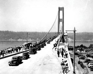
Contractors on the bridge were the Pacific Bridge Company of San Francisco, with the Bethlehem Steel Company furnishing and erecting the steel and spinning the wire cables. The contractors noticed that the span would move considerably in the wind when placing the deck, but Moisseiff assured them that it was not a problem. David L. Glenn, the Public Works Administration (PWA) field engineer, would not sign off on the acceptance of the bridge due to what he called faults in design, but he was over-ruled, and the PWA and the Washington State Toll Bridge approved of the bridge. It opened with a grand celebration on July 4, 1940, and everyone associated with the project praised its slender, gossamer-like structure.
The bridge, however, continued to exhibit vertical movements, galloping, and it became a sort of thrill ride as motorists drove across it to experience the longitudinal rippling motion of the deck, with many noting that oncoming automobiles appeared to vanish behind hills as the waves moved through the structure. As a result, it received the nickname “Galloping Gertie,” which did not please the Washington Toll Bridge Authority who worried about its movements. They requested Frederick B. Farquharson of the University of Washington engineering department to prepare a study of vertical oscillations in the bridge’s deck, hoping to discover a means to reduce the movements. He experimented with a 54-foot-long model of the bridge in a wind tunnel to determine its behavior under various wind speeds and directions. In May 1940, they installed hydraulic buffers between the deck and the towers to dampen longitudinal motion to show they were doing something. This was based upon work being done on the Bronx Whitestone Bridge in New York City that had 11-foot-deep plate girders for deck stiffening. Diagonal cable ties connecting the suspension cables to the stiffening girders were also placed on the main span with the hope of also minimizing the movements. But despite these measures, the structure continued to undulate in a vertical motion with moderate amplitudes under both modest and heavy winds. The WTBA contacted Moisseiff, who told them he had experienced similar, but smaller, movements on his Deer Island Bridge (with D. B. Steinman) in Maine and his Bronx-Whitestone Bridge (with O. H. Ammann) in New York City. Apparently, he had no suggestions on how to minimize the movements.
After talking to Eldridge, a newspaper article reported, “There is nothing unusual about the antics of the Narrows span, Eldridge states, although those of this bridge are aggravated by its slender proportions necessitated by shortage of funds with which to build it. The Narrows span is narrower in proportion to its length than any bridge in the world, and at the same time, the girders, which would be expected to stiffen it, are shallower than those of any similar structure. The Whitestone Bridge, recently completed in New York, has as much bounce as the Narrows bridge, according to reports but, instead of publicizing it, New Yorkers have done everything they could to keep it quiet. There is nothing dangerous about the performance, which in no way affects the strength or safety of the Narrows span, Mr. Eldridge states. Aside from affording a basis for tall tales of the span’s cavorting, the bridge’s bouncing is having no real effect whatever. Motion in the span deck is caused by the center span being swung out of line by a puff of air. This draws the tops of the towers together, lifting the two outside spans; as the center span swings back, the shore end spans drop, starting the wave motion, which is further aggravated by swinging of the center span. As the center span is designed to raise and lower 10 feet or more, due to changes in temperature, the four-foot hop of the bounce does not put any strain on it, which the design does not take care of with a large factor of safety.”
After completing preliminary wind tunnel tests, Professor Farquharson suggested several modifications be made to the structure to possibly cure its susceptibility to wind movements. They had already placed tie-down cables in the side-spans, attaching them to concrete anchorages, but they snapped during the first windstorm. He recommended the streamlining of the plate girder’s shape with “a rounded out-rigger type buffer along the side of the bridge to prevent the wind from hitting the flat side of the bridge full force,” believing, correctly, that its large flat surfaces contributed to the oscillating movements. He also suggested drilling a series of holes along the plate girders to let the wind pass through them. They accepted the recommendation to add the rounded out-riggers to the outer surfaces of the girders and had ordered the steel to implement the recommendation in early November. Unfortunately, they never had a chance to modify the girders as the bridge collapsed on November 7, 1940.
An upcoming issue will include more on the failure and the subsequent investigation.■