
Part 2
A recent seismic retrofit project provided an opportunity to test an interior concrete column retrofit with a three-sided, fiber-reinforced polymer (FRP) wrap with FRP through-anchors on the fourth side. The testing demonstrated the effectiveness of this application, which could be applied to columns or beams with deficient shear strength in situations where site conditions prevent access to one side of the member. Please refer to Part 1 (STRUCTURE, January 2022) for additional testing information.
Project Background
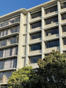
The University of California, San Francisco’s (UCSF) Mount Zion Housing is a concrete apartment building constructed in 1968, with seven stories above grade plus a basement. The floor plan above grade is T-shaped and comprises approximately 14,000 square feet at each level. Rectangular cast-in-place concrete columns support post-tensioned concrete floor slabs. Full-height concrete structural walls, located at the building’s corners and around a central core, serve as the lateral-force-resisting elements.
The apartment building was donated to UCSF; the retrofitted building will serve as faculty and staff housing at the Mount Zion campus.
Seismic Deficiencies
The structure has seismic deficiencies typical of a concrete building from the 1960s. The original gravity system has limited ductility capacity to withstand lateral deformation. The interior columns lack closely spaced ties over most of the column height. They are governed by non-ductile shear failure, as assessed by ASCE 41-17, Seismic Evaluation and Retrofit of Existing Buildings. The seven-inch-thick floor slabs have no bottom reinforcement that extends through the columns and thus are susceptible to punching shear failure under lateral seismic displacement of the building. Exterior columns are captured by deep spandrel beams at all levels, creating a short-column effect.
Seismic Evaluation Criteria and Methods
The retrofit design follows the requirements of the California Building Code and the ASCE 41-17 standard. The retrofit targets performance objectives of Collapse Prevention under the BSE-C (975-year return period) earthquake level and Life Safety under the BSE-R (225-year) level. As is typical, the first of these two objectives governs the retrofit design.
Tipping Structural Engineers is the project’s structural engineer of record (SEOR). Consistent with UCSF seismic policy, they employed a nonlinear response-history analysis (NLRHA) for the seismic evaluation and retrofit design. The analysis model was built using the CSI Perform 3-D software and includes the concrete shear walls, basement walls, floor diaphragms and collector elements, and vertical soil springs at the foundation. The nonlinear actions that are modeled include wall flexure and axial behavior (using vertical fiber elements), existing wall shear behavior, collector yield (elastic perfectly-plastic), and soil springs (tri-linear). Actions intended to remain elastic include new wall shear behavior and diaphragm shear. The analysis was carried out using expected material properties for concrete and reinforcement.
Interior Columns
A column tree sub-model was built in Perform 3-D and constrained for lateral displacement to the primary analysis model to determine shear deformation demands for the interior columns. Nonlinear static (pushover) loads were applied to the center of mass at each level to impose the building’s displaced shape onto the column tree. The floor slabs and columns were modeled as frame members with moment hinges.
Comparing the results of this analysis to a hand calculation for shear demand based on probable slab moment confirmed that the model provided a conservative demand. The existing columns had only half of the required shear capacity (based on ASCE 41-17) needed to withstand the expected seismic displacements.
Seismic Retrofit Measures
Retrofit measures were applied to the exterior of the building and interior columns to address the seismic deficiencies (Figure 11 and Figure 12).
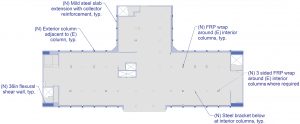
At the exterior, a concrete exoskeleton was designed to be constructed against the face of the pier-and-spandrel façade. The exoskeleton included four new or thickened planar structural walls, columns constructed against each existing exterior column, and collector beams constructed against the spandrels. The structural walls reduce the story drift demand and improve the building’s deformation profile over its height. The exterior columns provide a backup load path for gravity load at the vulnerable captured columns. The collectors tie the vertical elements to the existing floor diaphragms.
The interior retrofit uses steel brackets attached to the tops of interior columns to support the slab above to mitigate the consequences of punching shear failure under lateral displacement of the building. Additionally, FRP wrapping is used at interior columns to prevent column shear failure under seismic deformation.
FRP Wrap at Interior Columns
In the U.S., seismic evaluation and retrofit practice prior to the late 1990s emphasized adding strength and stiffness to the seismic-force-resisting system of buildings and often did not adequately address the vulnerability of gravity columns.
Current retrofit practice for concrete buildings now focuses on protecting gravity columns from brittle failure, which can occur under the lateral deformation demand imposed by earthquake ground motions. Wrapping or “jacketing” of concrete columns using fiber-reinforced polymer (FRP) or steel is now commonly a part of concrete building retrofitting. Retrofitting a square or rectangular column section to allow for high compression strain often requires a jacket with an elliptical cross-section to provide confinement. The space between the column and jacket is filled with grout. However, if the principal deficiency is shear strength, testing has shown the effectiveness of slightly rounding the concrete corners and applying FRP directly to the perimeter of the square or rectangular column. The fibers of the FRP (either carbon or glass fibers) are horizontal-only to provide shear strength without directly increasing flexural strength.
Three-Sided FRP Wrap
At most of the interior columns in the project, FRP wrap could be applied around the entire column perimeter (all four faces). However, existing interferences at nearly 30% of the interior columns prevented use of a full four-sided wrap, driving the need for a three-sided option. UCSF, the SEOR, and the peer reviewers agreed that the designer of a three-sided FRP wrap would have to provide testing validation of the structural effectiveness of the proposed detail. This was a requirement of the construction documents.
The FRP subcontractor selected Simpson Strong-Tie as the FRP supplier and designer; Simpson was responsible for providing test results to meet the performance requirements.
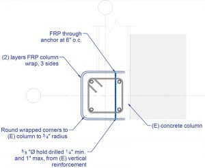
Simpson proposed a solution using FRP through-anchors in place of the fourth side of wrapping (Figure 13). Such through-anchors are used in other FRP wrapping applications, such as for long narrow columns. Another FRP supplier and designer, Aegion/Fyfe, has also tested a three-sided FRP wrap using an approach that includes through-anchors.
Column Testing Program
The purpose of the test program was to determine the effectiveness of a three-sided FRP wrap in preventing a shear failure. The testing was carried out at Simpson Strong-Tie’s Tyrell Gilb Research Laboratory in Stockton, CA. The test was of a column similar to the interior columns of the buildings that were to receive the proposed three-sided FRP wrap. The control column design, test setup, test procedures, and displacement loading protocols were documented in detail in Part 1 of this series (STRUCTURE, January 2022).
Test Specimens
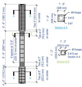
The testing included one control column (Figure 14), i.e., a column without retrofitting, and two identical specimens of a column with the three-sided FRP retrofit.
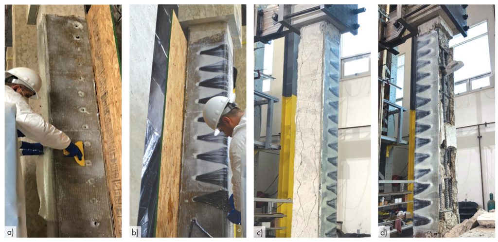
After the specimens were cast and cured, two were placed in an upright position. The three-sided FRP wrap was then installed under conditions that represented the field conditions, including a sheet of oriented strand board that blocked access to the fourth side in a manner similar to the field conditions (Figures 15a and 15b).
The FRP testing and quality control measures required for the field installation were also applied to the laboratory specimens.
Test Setup and Procedures
The columns were tested under imposed lateral displacement, with fixed-fixed end conditions. A cyclic-static history of lateral displacement was applied to the specimens. Axial load was not applied.
The control column was tested first. The second test was of one of the retrofitted columns tested perpendicular to the through-anchors. The third test was of the other retrofitted column, tested parallel to the through-anchors.
Successful Test Definition
Before testing, the SEOR and peer reviewer agreed that, for the retrofit to be judged effective, it had to, as a minimum:
- Prevent a shear failure of the column that would otherwise occur by increasing shear strength to an extent such that flexural yielding governs the nonlinear behavior, and
- Improve the deformation capacity of the column so that it achieves a story drift ratio for the building that meets the Collapse Prevention requirements of the California Building Code for state-owned buildings.
The success criteria had to be met for each plan direction of testing. For this building, the target story drift for the second criterion was 0.037. This was based on the lateral story drift demand from the nonlinear response history analysis, taking the worst story and worst of 11 records for BSE-C ground motions.
Test Results
The control column failed in the behavior mode predicted: shear failure in diagonal tension in the mid-height region of the column that had a tie spacing of 12.8 inches. The shear demand at failure was 40 kips. The previous article discussed the control column test results and implications in detail. The testing of the retrofitted columns demonstrated the effectiveness of the three-sided FRP wrap. The retrofit met the criteria for success defined prior to the test.
Prevention of Shear Failure
The retrofit prevented the shear failure that occurred in the control column by increasing shear strength and enabling flexural yielding to govern the nonlinear behavior (Figures 15c and 15d).
Having prevented shear failure, peak load occurred based on ductile flexural behavior, although the column with loading perpendicular to through-anchors exhibited reduced capacity from spalling of the cover concrete.
Peak lateral strength increased from 40 kips for the control (un-retrofitted) column to between 52 and 60 kips for the retrofitted columns, for which shear failure did not occur (33% and 54% of additional lateral strength).
Deformation Capacity
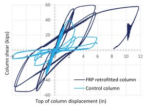
The retrofitted columns showed the ability to displace beyond a story drift ratio of 0.05 without substantial damage that would create a risk of collapse. Furthermore, the column suffered no strength degradation for loading parallel to through-anchors even up to a story drift ratio of 0.11 (Figure 16).
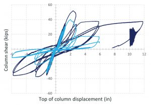
Spalling occurred on the unwrapped face as the cover concrete was subjected to high compression strains for the column with loading perpendicular to through-anchors. The spalling of the cover concrete reduced the effective section depth for flexure. As a result, the lateral strength of the column reduced from its peak strength of 52 kips to a strength of 37 kips, which it maintained without further degradation up to the maximum story drift ratio of 0.11 (Figure 17).
This was a success, given that retrofit was designed for shear strength and not confinement against high compression strain. The moment-curvature analyses show that compression strains would not have been as high for columns with less longitudinal reinforcement, and spalling would have been less likely.
Findings and Conclusions
The testing showed the effectiveness of the three-sided FRP wrap configured with through-anchors near the unwrapped side. The retrofit prevented shear failure and substantially increased the column’s ability to undergo large lateral deformations. However, for columns with heavy longitudinal reinforcement and/or high axial load, cover concrete may be prone to spalling on the unwrapped side.■
References are included in the online PDF version of the article at STRUCTUREmag.org.
References
Structural Engineering Institute, American Society of Civil Engineers (2017), ASCE/SEI, 41-17: Seismic evaluation and retrofit of existing buildings, American Society of Civil Engineers, Reston, VA.
California Building Standards Commission (2019), 2019 California Administrative Code, California Code of Regulations, Title 24, Parts 1 and 2, International Code Council, Washington, D.C.
ACI 318-19, Building Code Requirements for Structural Concrete and Commentary.
Project Team
Owner: UCSF
Structural Engineer: Tipping Structural Engineers
Architect: Gelfand Partners Architects
Seismic Peer Review and Structural Plan Check: Maffei Structural Engineering, Estructure, and the UCSF Seismic Review Committee, consultants to UCSF Building Permit Services.
Contractor: Webcor
Subcontractor for FRP: FD Thomas Structural Specialties
Design of FRP and Laboratory Testing: Simpson Strong-Tie
Testing Compliance: TEI