
When the University of California, Los Angeles (UCLA) identified a need to expand their existing Anderson Graduate School of Management (AGSM), they were presented with a clear challenge: the lack of a viable location to place a new building on a campus with limited square footage. The solution was to construct the new building entirely upon an existing parking structure adjacent to the School of Management.
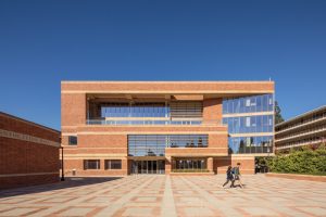
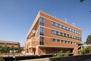
The new UCLA Marion Anderson Hall (MAH) is an $80M project that provides a LEED platinum, 64,000-square-foot, 4-story building to expand the capacity of the existing AGSM initially built in 1995. The new building supports large classroom areas, workspaces, offices, and sizeable auditorium/event spaces. MAH was shaped and cladded to blend effortlessly with the adjacent complex of the AGSM buildings (Figure 1).
The building presented the unique challenge of being constructed entirely upon an existing 6-story 430,000-square-foot reinforced concrete parking structure, which remained partially open throughout the construction of the new building above. The parking structure was originally built in 1959 but had seen multiple major structural updates over the decades. Updates included the complete removal of an adjacent hillside and associated perimeter retaining walls, voluntary seismic retrofits, and even large floorplate sections removed to accommodate the original AGSM construction.
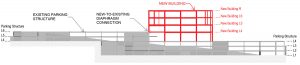
The existing parking structure is constructed on a sloping site, such that the top two levels are offset from the bottom 4 levels. The MAH building is constructed directly at this step between the upper and lower levels. Therefore, the new building has vertical support at two different elevations of the existing parking structure; each serves as an entrance – the 4th and the 6th floor of the parking structure. The new building also ties in horizontally to the 6th floor of the parking structure, which aligns with the first raised floor of the new building (Figure 2).
Seismic Criteria
The University of California Seismic Safety policy (UCSSP) provides the governing seismic criteria for all buildings on University of California premises. The project is located in an area of high seismic hazard, and seismic design criteria for both the new building and seismic retrofit of the existing parking structure were per the UCSSP.
For new buildings, UCSSP requires compliance with the current seismic provisions of the California Building Code (CBC). Because the new MAH building contained adult education facilities with an occupant load greater than 500, the building was assigned to Risk Category III per CBC Table 1604.5. In addition, the existing parking structure completely supported the new MAH building above, and consequently, it was also treated as Risk Category III.
For existing buildings, the UCSSP generally refers to the CBC, which in turn references the American Society of Civil Engineers’ ASCE 41, Seismic Evaluation and Retrofit of Existing Buildings. The ASCE 41 performance objectives for the existing building were “Damage Control” @ BSE-1N and “Limited Safety” @ BSE-2N. BSE-1N/2N are ASCE 41 hazard levels that correlate to the Design Basis Earthquake (DBE) and Risk-Targeted Maximum Considered Earthquake (MCER) from ASCE 7, Minimum Design Loads for Buildings and Other Structures. The UCSSP also required an independent seismic peer review which was conducted for the overall project, reviewing both the new building and the retrofit of the existing building.
The overall project included a new structure upon an existing structure, vertical and horizontal combinations of lateral systems of different types and eras, horizontal connections of new floors to existing floors, and gravity and seismic demands delivered from the new structure above to the existing structure below. The seismic criteria also spanned across both ASCE 7 and ASCE 41. A customized two-tier design/analysis procedure incorporating both ASCE 7 and ASCE 41 was utilized to accurately capture the structures’ behavior to accommodate these unique circumstances while also satisfying the UCSSP requirements for both new and existing structures. The first tier consisted of a linear dynamic analysis for the new building design per ASCE 7, using the typical SMRF design coefficients of R = 8, Ω = 3, Cd = 5.5. This analysis was used to design the lateral system of the new structure, but the model included the entire existing parking structure below to capture its impact on the global behavior and demands adequately. The second tier of analysis was a full-building nonlinear time-history response analysis per ASCE 41. This analysis was utilized to evaluate and retrofit the existing parking structure to the ASCE 41 performance objectives noted above. It also provided supplemental verification of the new building’s seismic design to these same objectives when explicit nonlinear hysteretic behavior was included in both the new and existing buildings.
The New Building
The structural system for the new MAH building consists of concrete-filled metal deck over steel framing, with a seismic system comprised of Steel Special Moment Resisting Frames (SMRF) with Reduced Beam Section (RBS) connections. Moment Frame beams were typically W30x, with moment frame columns typically using heavy W24x or built-up box columns. All columns of the new building were spaced at a 27-foot x 30-foot typical grid to match the existing parking structure grid and land directly upon the existing concrete columns. In addition, to increase the floor area of the new structure beyond this grid, multiple sides of the floorplate provided perimeter cantilevers typically 15 feet long.
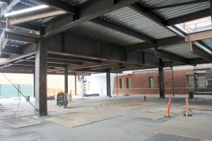
Multiple long-span transfer beams were required within the new building to accommodate the large column-free zones for auditorium/event spaces. This included the transfer of Special Moment Frame Columns, resulting in large, deep transfer beams requiring installation in multiple pieces and field-spliced once installed in place (Figure 3). The largest of these transfer beams spanned 54 feet while supporting an SMRF column at its midpoint and was a custom 60-inch-deep shape that weighed over 800 pounds per linear foot.
The layout also required multiple bi-axial SMRF hollow box columns that received two or more beams in perpendicular directions. These box columns were fabricated using electroslag procedures to accommodate the typical continuity plates required for RBS connections inside the boxes.
Retrofit of the Existing Parking Structure
The existing parking structure required a unique and extensive retrofit to upgrade to current UCSSP requirements while supporting the gravity and seismic demands imparted from the new building above. The existing structure consists of 9-inch-thick flat reinforced concrete slabs with sloping drop caps at circular columns, along with some interior and perimeter concrete shear walls. Some of the shear walls had been seismically retrofitted over the years with Fiber Reinforced Polymer (FRP) wrap or shotcrete. However, these retrofits accounted only for the parking structure’s own seismic demand and were based on different performance objectives and a less stringent Risk Category. Additionally, walls were unevenly distributed throughout the parking structure due to past renovations. With the new MAH building constructed above, the entire seismic base shear of the new building above would be transferred into the existing parking structure before reaching the foundation.
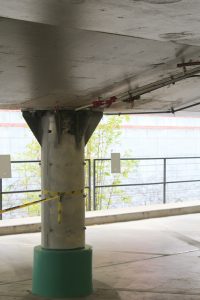
The existing concrete columns required strengthening to support the demands delivered from the columns of the new building above. Existing columns seeing compression-only loads from above were strengthened with either FRP or concrete jacketing. Columns seeing compression/tension loads from above were strengthened with steel jackets with customized top connection plates to receive the anchor bolts from the SMRF column above (Figure 4).
The existing slabs received significant diaphragm strengthening, predominantly in the form of FRP on the top and/or bottom of the slab. FRP application was chosen as the typical diaphragm strengthening material to maintain head-height requirements of the parking stories, which were already short in height. This FRP strengthening was predominantly seismic and was utilized for both collectors and diaphragm shear strengthening. The slabs also received a significant connection at the new building’s second floor, essentially “stitching” the new and existing diaphragms together at this elevation. This was achieved by chipping out the concrete of the existing slab while leaving the existing rebar in place and then re-pouring a heavily reinforced connection zone with new rebar coupled onto the existing rebar.
The seismic demand was transferred from the parking structure diaphragm to multiple existing and new reinforced concrete shear walls. The new walls were constructed by chipping out a slot in the existing slab to place the new rebar and concrete while leaving the existing slab rebar in place. During this process, the existing slab was supported with temporary shoring. Multiple existing concrete shear walls were also retrofitted with either supplemental FRP wrap or shotcrete.
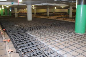
The typical existing foundation consisted of square isolated spread concrete footings. The majority of footings below the new building and those below new/retrofitted shear walls required strengthening. The foundation strengthening consisted of increasing individual footing areas and/or increasing footing depth by adding supplemental anchors, rebar, and concrete to the perimeter and/or top of footings. Where demands were largest, or new concrete shear walls were introduced, multiple footings were connected together to create new large combined footings (Figure 5).
Conclusion
The new Marion Anderson Hall (Figure 6) provided a sizeable expansion to the Anderson School of Management. The location and exterior façade provide a continuous extension of the original buildings, resulting in the perfect blend of the desired function with a matching aesthetic. The challenges of constructing an entirely new building on an existing parking structure were numerous – but close coordination between the design team, contractor, and client resulted in a great success.■
Project Team
Owner: University of California
Structural Engineer of Record: Nabih Youssef Structural Engineers
Executive Architect: Gensler
Design Architect: Pei Cobb Freed & Partners
General Contractor: PCL