
Center for Computing & Data Sciences Building
Located on Commonwealth Avenue, the Center for Computing & Data Sciences rises dramatically above the central campus of Boston University. Consisting of a 19-story, 305-foot-tall tower, and 5-story podium, the building is a hub for the campus and a showcase for the departments of Mathematics & Statistics, Computer Science, the interdisciplinary faculty of Computing & Data Sciences, and the Rafik B Hariri Institute for Computing and Computational Science & Engineering. Designed by internationally renowned design firm KPMB Architects of Toronto, Canada, the Center for Computing & Data Sciences capitalizes on its location in the heart of campus to create an inviting meeting place. The design of the building encourages collaboration and innovation between disciplines by creating vertically stacked research “neighborhoods” with staggered green-roofed terraces, interconnecting feature stairs, and generous public spaces.
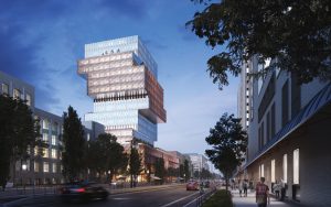
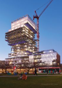
The podium houses student-focused facilities and amenities, including much-needed study spaces. The dynamic ground floor level enlivens and extends the streetscape. The key sustainability and resilience goals were fostered throughout BU’s design, resulting in one of the first large fossil-fuel-free buildings in Boston, aligning with the campus climate action plan with a target of LEED Platinum. The transparency and porosity of the building’s envelope displays the elegance and complexity of the cantilevered steel structure and acts as a beacon on the Charles River skyline (Figure 1). Teaming on the design to bring the building structure to reality are structural engineering firms Entuitive of Toronto, Canada, and LeMessurier of Boston, Massachusetts.
Common to Boston, the site is on reclaimed land from the second half of the 19th century. Originally part of the Back Bay, the site is underlaid with 6 to 15 feet of miscellaneous fills located over a 5- to 10-foot layer of organic deposits. Below the organic layer is a 7- to 16-foot glacier deposited sand layer that is a common layer for supporting the timber piles of historic Boston buildings of the late 19th and early 20th century. Below the sand layer is 150 to 165 feet of marine deposited clay with bedrock below. Thus, the site represents one of the deepest locations in Boston to bedrock.
The building consists of two main portions: the 19-story tower at the west side of the site with overall plan dimensions of 140 by 140 feet with a two-story deep basement, and a 5-story podium at the east side with plan dimensions of 70 by 170 feet with a one-story basement. Haley and Aldrich conducted the geotechnical exploratory program and worked with the design team and Suffolk construction to select the appropriate foundation system. The analysis focused on two primary foundation schemes: deep load-bearing slurry wall elements (LBE) extending to bedrock and a mat slab foundation. Working with the construction manager Suffolk, it was determined that a mat foundation would save over $5 million compared to the LBE foundations.
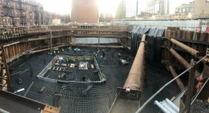
The 19-story tower height was close to the limit acceptable for a mat foundation. Tower loads had to be limited by optimizing the concrete core plan size and wall thickness and using lightweight concrete slabs on metal deck to realize the savings with a mat foundation. A 5-foot mat slab bearing 40 feet below grade on the marine clay, and thickening to 6 to 9 feet under the core walls (Figure 3), was utilized at the tower. The building weight was reduced to limit bearing pressures under dead and live load to a maximum of 6 ksf under the core with an average of 4.5 ksf under the tower footprint. A 3.5-foot mat slab bearing on the sand layer was provided below the podium. Approximately 1 to 1½ inches of elastic settlement and an additional ½ to 1 inch of long-term settlement is predicted at the tower mat slab, while ¼ to ½ inch of total elastic settlement and up to an additional ½ inch of long-term settlement is calculated at the podium.
To address resiliency and the Boston University Climate Action Plan, the ground floor was set 1 foot above the project design flood elevation, 5 feet above the Boston Planning & Development Agency design flood elevation. Building weight under the 19-story tower was sufficient to resist hydrostatic pressures from the design flood elevation. 40-ton tension mini-piles are provided below the 5-story podium to resist hydrostatic pressures from the design flood elevation.
Responding to the building programming requirements and compact floor plate, the lateral forces resistance system in the tower consists of a slender concrete shear wall core (Figure 4). The core footprint is 52 by 30.5 feet with two 52-foot-long walls in the east-west direction and three 30.5-foot-long walls north-south. The total core height is 338 feet above the top of the mat foundation, with a height-to-width ratio of approximately 11 to 1. As noted, the soil conditions required the superstructure to be as light as possible to limit short and long-term settlements and keep the subgrade soil stresses below the allowable values. Therefore, the core wall was limited to 14 inches thick to help achieve the weight reductions required to meet the soil pressure and settlement limits. High strength, self-consolidating concrete with a strength f´c = 10,000 psi at the base transitioning to f´c = 8,000 psi at the top was used for the core.
Contrary to conventional construction of cast-in-place framed concrete slabs within the core, 3¼-inch lightweight concrete slabs supported by a 3-inch deep composite metal deck are employed to reduce the total weight. The 5-story podium has its own lateral force resistance system comprised of a structural steel elevator and stair “core” made up of concentric braced frames.
The lateral loads on the building are wind controlled, with Exposure C. The 14-inch shear wall thicknesses necessitated high-strength threaded #14 Grade 105 steel reinforcing at boundary elements. The large diameter reinforcement helped eliminate rebar congestion in the core. In addition, staggered mechanical splices were used for the boundary element steel along the height of the core walls, further helping reduce congestion and conflicts with various other building components, including embed plates.
The three slender north-south walls contained door and MEP penetrations, creating a challenging scenario for the design of these wall and link beams. Typical link beams occur in the center of the wall and contained MEP penetrations to allow services out of the core. This placed significant constraints on the placement of rebar within the link beams. In addition, the narrow thickness of the wall and link beams precluded embedded structural steel sections in the link beams at the lower levels to help carry the shear/flexure demands. Instead, 1¼- to 1½-inch-thick grade 50 steel plates are embedded in the link beams at lower levels to provide adequate strength and stiffness to the link beam sections. The plates are made to act compositely with the concrete with headed studs on each side of the plate. Careful coordination with architectural, mechanical, and electrical teams was required to place the penetrations through these plates. The effort and care of planning these link beams paid off during the construction phase, with few conflicts resulting from rebar placement and/or wall penetrations.
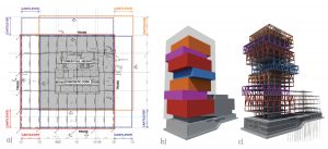
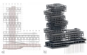
The tower has typical 115- by 115-foot floor plates of five 23-foot bay modules in the north-south and east-west directions. The floor plans have footprints that line up with each other vertically for no more than three floors consecutively. The center four-bay by four-bay portions of the tower supports all tower gravity loads and includes a concrete core and columns that run continuous the full height of the tower (Figure 5a).
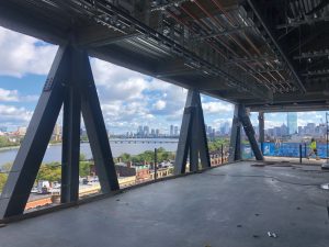
The architectural massing of the building uses shifting, free-floating volumes to create outdoor terraces associated with research “neighborhoods” that capitalize on the spectacular views from all sides of the tower. The overall building footprint of 138- by 138-foot comprises floor plates made up of six 23-foot bay modules in the north-south and east-west directions (Figure 5a). Floor plates shift by one bay in a counter-clockwise arrangement around the core every two or three stories. This creates an offset block layout of masses, with different volumes cantilevering over the floors below (Figure 5b). Columns in this area do not extend to grade. Two-story deep trusses made of wide flange steel and located along the perimeter support these volumes. Typically, a single truss spans the full length of the building, which is, in turn, supported by a truss in the perpendicular direction that cantilevers a single bay (Figure 5c). This results in a mixture of traditionally supported and hung floors. This careful placement of the trusses creates a load path that guides the gravity loads back towards the columns that run continuous through the height of the building. The architecturally exposed steel truss framing and connections are expressed visually and are fireproofed with intumescent paint (Figure 6).
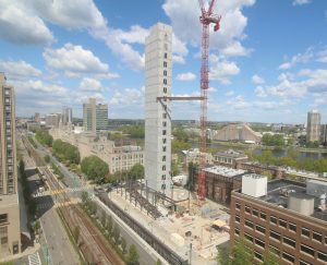
The cantilever steel framing was superelevated for 80% of the predicted dead load deflections (Figure 7).
Suffolk Construction, Prime Steel Erecting, and their erection engineer, Simon Design Engineering, worked closely with the design team on the temporary shoring and jacking systems. Full height shoring was provided to allow for erection of the steel. Jacking boxes as part of the shoring system were included to allow for superelevation. Hydraulic jacks were utilized to unload the shoring and uniformly load the cantilever framing.
Opening in late 2022, the Boston University Center for Computing & Data Sciences building will foster innovation and collaboration as a leader in Computing & Data Sciences. The building is set to demonstrate Boston University’s commitment to sustainability, resiliency, and social responsibility.
Part 2 will focus on sustainability, life cycle assessment, and opportunities realized to reduce the embodied carbon of the building structure.■
Project Team
Structural Engineers: LeMessurier, Entuitive
Architect: KPMB Architects
Contractor: Suffolk Construction
Steel Fabricator: Canatal Industries
Steel Erector: Prime Steel Erecting Inc
Concrete Contractor: S&F Concrete Contractors