
Often Overlooked and Misunderstood
For over 40 years, the traditional pour strip in concrete construction has been an issue of contention between the engineer of record (EOR) and the contractor, and this challenge continues today. The EOR desires a high-quality slab, which requires more pour strips that are left open longer. The contractor wants faster construction, which requires fewer pour strips and pouring them back sooner. Shrinkage and restraint-to-shortening (RTS) are at the core of this age-old dilemma, and EORs should not have to sacrifice quality for cost and schedule.
Cost, quality, and schedule are significant factors, and most people in construction say you can only get two out of three on a project. However, for traditional pour strip construction, you may only get one if higher quality is chosen. Particularly common in post-tensioned (PT) concrete construction, pour strip leave outs cause either significant delays or poor quality, and they are always a safety concern because of the large gaping hole through floor slabs.
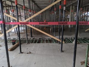
The pour strip or leave out (Figure 1) is a 3-foot to 8-foot gap in a floor slab, which is often left open three to four levels below the floor being placed. Pour strips have a long successful history of being used in reinforced concrete (RC) structures before the popularity of PT began in the 1960s. PT pour strips have even more impact from RTS due to the additional volume change from elastic shortening and creep caused by post-tensioning compression forces restrained by structural elements (i.e., shear walls and other stiff vertical members). Temperature change during construction can also significantly contribute to slab cracking, especially during winter when the slab is heated for curing but removed after a few days. All volume change components contribute to cracking and poor slab performance if not dealt with appropriately.
The industry solution used by EORs to allow for this shortening has been a traditional pour strip, which relieves the strain in the slab and is wide enough for a reinforcement lap splice and PT tendon jacking. The biggest complaint from contractors of the traditional pour strip is that it delays construction. Forms of gapless pour strip or strain-relief-joint (SRJ) solutions can resolve the age-old pour strip dilemma and remove contention between the EOR and contractor.
Volume Change and RTS
Volume change and RTS are challenging aspects of concrete construction and are often misunderstood. They are even more challenging when PT is involved. The issue is the tensile stress created when slab shortening is restrained by stiff structural elements. A properly designed pour strip temporarily interrupts slab continuity between the stiff elements, lowers RTS, and allows for volume change. Since creep and shrinkage strains increase with time, cracking can be reduced by keeping the pour strip open longer. It is common for EORs to require a pour strip to remain open for 28 or 56 days and sometimes even longer for better performance. Serviceability is the primary design concern, and PT slabs are not designed to crack. Excessive cracking leads to deflection, vibration, and corrosion (parking garages) problems, leading to architectural complications.
Pour Strip Locations
For years, the typical pour strip has been part of the Post-Tensioning Institute’s (PTI) Post-Tensioning Manual. When poured back, the basic structural function of a pour strip is to create reinforcement continuity from one side of the leave-out to the other. This provides load transfer for both vertical (such as slab moment and shear) and horizontal loads (like diaphragm, horizontal shear, and drag forces).
Many EORs designing either RC or PT slabs believe that forming and shoring is a means and methods responsibility of the contractor. This is not entirely true because where EORs place pour strips, how they design them, and when they can be poured back dictates how the contractor must build them. Definitions of reshoring and backshoring can be found in ACI 347, Guide for Shoring/Reshoring of Concrete Multistory Buildings. Where slabs are self-supporting, less expensive reshoring can be used, and slabs that are not self-supporting require more expensive backshoring. PT slabs can be designed as self-supporting, which is not practical for RC slabs, and always require backshoring. A gapless pour strip needs to provide for slab shortening and all the structural functionality of a traditional pour strip. It must create ductile reinforcement continuation for both vertical and horizontal load transfer.
In the case of PT with a traditional pour strip, a mid-span location (between columns) with self-supporting slabs is the most desirable for construction because it only requires reshoring. A slight increase in PT at the bays near the pour strip allows for self-supporting cantilevered slabs without costly backshoring. A mid-span location in RC requires backshoring on both sides of the pour strip. Therefore, most pour strips in RC are placed at a one-fifth-span location, which requires only the long, four-fifths-span to be backshored.
When a concrete contractor is not directly involved in the design process, EORs often select a one-fifth-span location for the pour strip. This is because, at this location, the flexural moment demand is near zero; it is a point of contraflexure where minimal slab reinforcement is required. Unfortunately, this typically creates a four-fifths-span that cannot be self-supporting, which requires expensive backshoring. Contractors who understand backshoring know that the associated costs and schedule delays far exceed any savings in reinforcing steel and PT. Furthermore, backshoring must stay in place until the concrete structure is complete.
Often Overlooked
EORs often overlook construction issues created in their designs. Pour strip locations, how they are designed, and when they can be poured back drives the formwork and shoring requirements. Pour strip construction is not just a means and methods responsibility of the contractor. The pour strip design has a trickle-down effect that delays every other trade and results in longer, more expensive construction projects. The concrete structure is on a project’s critical path, and the pour strip is on the critical path of the concrete structure.
Beyond the apparent cost, quality, and schedule issues traditional pour strips present, they also create a safety hazard. The number one concern on a construction site is safety. Having a large gap in the floor is a significant obstacle that must be protected and bridged to prevent injuries.
Gapless Pour Strips
A gapless pour strip that eliminates the large leave-out but still allows for volume change and structural continuity would take the pour strip off the critical path and be the best of both worlds. This type of pour strip would allow EORs to achieve higher quality slabs without increasing cost or lengthening schedules.
When a traditional pour strip is poured back, it achieves two structural functions (transfer of vertical and horizontal loads) utilizing an ACI 318-permitted lap splice providing ductile reinforcing steel continuation (ACI 318, Building Code Requirements for Structural Concrete and Commentary). For a gapless pour strip to be substituted for a traditional pour strip, it must have the same structural functionality.
A gapless pour strip lowers costs, improves quality, and shortens schedules. The length of time a gap is left open is no longer an issue; thus, quality is improved without expense. Additionally, there is no trickle-down effect that delays other trades, and safety concerns are eliminated. But how can a gapless pour strip be achieved?
Lockable Dowels
Some have used lockable dowels to create a gapless pour strip. They are typically located at a one-fifth-span since they do not provide reinforcing continuation and instead act as a shear dowel. The lockable dowel can support a self-supporting four-fifths-span, which allows for less-costly reshoring versus expensive backshoring. However, this is only part of the story as it does not provide structural continuity like the traditional pour strip.
Since this product is a dowel (with limited non-ductile pull-out much like an expansion bolt), it must be used when ductile reinforcing steel continuation is not a concern. Most structural engineers call this an expansion joint where diaphragm chord steel is interrupted. This does not replace all of the vertical or horizontal loading functions provided by a traditional pour strip.
Fire ratings are typically required in concrete slabs. Beyond its inability to transfer loads like a traditional pour strip, the lockable dowel uses an epoxy grout, which is combustible and turns soft/plastic around 150°F. Therefore, EORs need to be careful using the lockable dowel when fire ratings are required.
Although the lockable dowel creates a gapless pour strip, it falls short and does not provide the same structural functions as a traditional pour strip. Structural engineers must be careful when evaluating the lockable dowel because it cannot transfer the ductile reinforcement needed to withstand all vertical and horizontal loads, including diaphragm chord continuation. In other words, the lockable dowel is only a partial substitute for a traditional pour strip.
Mechanical Splices
Steel reinforcement mechanical splice systems (known as rebar couplers) have a long, proven history of providing for the continuation of ductile reinforcing steel, dating back to the 1960s. Tens of millions have been successfully installed worldwide, including in high seismic zones. Since normal reinforcing bar lengths are far short of typical building dimensions, four ACI 318 code-permitted methods of splicing rebar provide reinforcement continuation: lap splices (used in traditional pour strips), mechanical splices (rebar couplers), butt-welded splices, and end-bearing splices.
Mechanical splices were first used in high seismic regions. They are now defined by ACI 318 as Type 1 (non-seismic) capable of developing 125% Fy (yield strength) and Type 2 (seismic) capable of developing 100% Fu (ultimate strength); this is also included in the required ICC-ES Acceptance Criteria for Mechanical Connector Systems for Steel Reinforcing Bars (AC133).
Mechanical couplers are made of steel or a combination of steel and concrete. Fire ratings for mechanical reinforcement splices installed in concrete are prescriptive (and the same as for rebar) according to the International Building Code (IBC) and ICC-ES (defined in Table 721.1 in the latest IBC).
A mechanical coupler is simply another ACI 318-permitted method of splicing reinforcing steel, much like a lap splice utilized by traditional pour strips. Could a unique mechanical rebar coupler that provides the same structural functionality as a traditional pour strip but allows for volume change be the solution to a gapless pour strip? Yes.
A New Solution
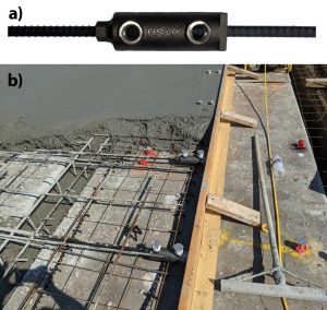
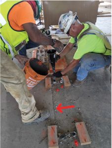
The PS=Ø® Mechanical Reinforcement Splice System (Figure 2) eliminates traditional pour strip leave-outs and maintains reinforcing continuity while allowing for volume change. It features a tapered thread on one end and a grout-filled sleeve on the other. The system meets ACI 318 Type 1 and Type 2 mechanical splice requirements and is ICC-ES approved (ICC-ESR 4213). PS=Ø stands for Pour Strip Zero and allows for free movement, longitudinal and transverse, to the SRJ until the coupler is grouted with a high-strength concrete grout (Figure 3). PS=Ø allows for the original EOR design of a traditional pour strip to be maintained, and since it is a simple substitution, no delegated design is required.
PS=Ø has the same structural functionality as a traditional pour strip but does not require a leave-out. It provides a load transfer of both vertical (such as slab moment and shear) and horizontal loads (like diaphragm, horizontal shear, and drag forces) by connecting ductile reinforcing from one side of the slab to the other using a code-permitted method of splicing rebar.
Applications
Both applications apply to one-fifth-span and mid-span locations.
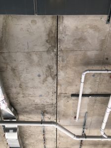
- The standard application (Figure 4) is where the second slab is poured directly against the first slab. Stressing can be done from either end of the first slab but only from the outside of the second slab.
- When a temporary leave out or stressing strip is needed, they can easily be added to the system between slabs or at a wall and adjacent slab, then poured back immediately after stressing. This can also be utilized in construction sequencing where a delayed, low-rise building is attached to an adjacent high-rise building.
Conclusion
The traditional pour strip has been the industry solution used by EORs to allow for volume change and relieve RTS in concrete slabs for decades. Although a good solution, it has been an issue of contention between EORs and contractors because of the construction problems it brings. Cost, quality, and schedule are essential aspects of building projects and pour strips have forced EORs to sacrifice quality for cost and schedule.
Real, lasting innovation in construction requires solutions that make designs better and construction more productive. Structural engineers developed PS=Ø to create a gapless pour strip or strain-relief-joint (SRJ) that provides high-quality slabs without increasing cost or lengthening schedules. With PS=Ø, overall projects costs and schedules are significantly reduced and safety is improved, making this rebar coupler an excellent innovation for concrete construction. Lower cost, higher quality, accelerated schedules, and improved safety are achieved. PS=Ø provides the same structural functionality as the traditional pour strip, making it an easy substitution for a gapless pour strip.■
References
Aalami, B., Shortening Calculations of Post-Tensioned Floor Systems, Adapt Technical Note, Adapt Corporation 2007.
Allred, B., “Issues in Post-Tensioned Construction,” Concrete Construction, January 2006, www.concreteconstruction.net/how-to/construction/issues-in-post-tensioned-construction_o
ACI Committee 209, Report of Factors Affecting Shrinkage and Creep of Hardened Concrete (ACI 209.1-05), American Concrete Institute, Farmington Hills, Michigan, 2005.
ACI Committee 318, Building Code Requirements for Structural Concrete (ACI 318-19) and Commentary on Building Code Requirements for Structural Concrete (ACI 318R-19), American Concrete Institute, Farmington Hills, Michigan, 2019.
ACI Committee 347, Guide to Formwork for Concrete (ACI 347R-14), American Concrete Institute, Farmington Hills, Michigan, 2014.
ACI Committee 347, Guide for Shoring/Reshoring of Concrete Multistory Buildings (ACI 347.2R-17), American Concrete Institute, Farmington Hills, MI, 2017, 28 pp.
ACI Committee 439.3R-07, Types of Mechanical Splices for Reinforcing Bars (ACI 439.3R-07), American Concrete Institute, Farmington Hills, Michigan, 2007.
Bordner Tanck, M., “Pour Strips and Constructability,” STRUCTURE magazine, April 2014, pp 46-47.
Guo, G., Joseph, L., M., and Bieberly, G., E., “Restraint Design of Cast-in-Place Post-Tensioned Underground Parking Structures,” PTI Journal, Post Tension Institute Farmington Hills, Michigan, August 2009, pp 5-17.
International Building Code, 2018, International Code Council. Inc., Country Club Hills, IL. ICC-Evaluation Service ESR 4213.
PTI Technical Advisory Board, 2006, Post Tensioning Manual, Sixth Edition, Post Tension Institute Farmington Hills, Michigan, 2006.