
Part 2: Foundations (Chapter 18)
This five-part series (Part 1, STRUCTURE, November 2021) includes discussion of significant structural changes to the 2021 International Building Code (IBC) by the International Code Council (ICC). This installment includes an overview of changes to Chapter 18 on foundations and soils. Only a portion of the total number of code changes to this chapter are discussed in this article. More information on the code changes discussed here can be found in the 2021 Significant Changes to the International Building Code, available from ICC.
IBC Chapter 18 provides criteria for geotechnical and structural considerations in selecting, designing, and installing foundation systems to support the loads imposed by the structure above. Basic requirements for all foundation types are provided, including requirements specific to shallow and deep foundations. The following modifications were approved for the 2021 IBC. Code text for each section is included with new text identified by underlining, followed by a brief description of the change significance.
Frost Protection at Required Exits
Frost protection for egress doors has been added to the foundation requirements.
1809.5.1 Frost Protection at Required Exits. Frost protection shall be provided at exterior landings for all required exits with outward swinging doors. Frost protection shall only be required to the extent necessary to ensure the unobstructed opening of the required exit doors.
Change Significance: Frost protection must now be provided for exterior landings at all required means-of-egress doors. In addition, where frost protection is required, landing areas immediately adjacent to egress doors must be provided with the same frost protection systems as the building being served by the exit. This protection is designed to prevent concrete landings from heaving, thereby compromising the normal operation of required egress doors. Such heaving actions can render an egress door entirely unusable.

Section 1809.5.1 is intended to provide heave protection only for the area of a landing immediately adjacent to exit doors and only for the area required to allow a door to swing open at least 90 degrees from a closed position. The remaining portions of a larger patio or sidewalk need not be provided with frost protection. Doors that do not swing – for example, a revolving door at a lobby entrance – do not require frost protection (Figure 1).
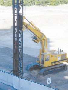
Helical Piles
Calculation of the allowable axial design load for helical piles has been clarified.
1810.3.3.1.9 Helical piles. The allowable axial design load, Pa, of helical piles shall be determined as follows:
Pa = 0.5Pu (Equation 18-4)
where Pu is the least value of:
-
- Base capacity plus shaft resistance of the helical pile. The base capacity is equal to the sum
Sumof the areas of the helical bearing plates times the ultimate bearing capacity of the soil or rock comprising the bearing stratum.The shaft resistance is equal to the area of the shaft above the uppermost helical bearing plate times the ultimate skin resistance. - Ultimate capacity determined from well-documented correlations with installation torque.
- Ultimate capacity determined from load tests when required by Section 1810.3.3.1.2.
- Ultimate axial capacity of pile shaft.
- Ultimate axial capacity of pile shaft couplings.
- Sum of the ultimate axial capacity of helical bearing plates affixed to pile.
- Base capacity plus shaft resistance of the helical pile. The base capacity is equal to the sum
Change Significance: Larger helical pile elements are now common, and shaft friction can play an important role for larger shaft diameters (Figure 2).
Pa, the base capacity plus the shaft resistance, may now be used when determining the allowable axial load. Shaft resistance is the shaft area multiplied by the shaft’s ultimate skin resistance for the length above the shallowest bearing plate. Base capacity is the soil or rock ultimate bearing capacity in the bearing layer multiplied by the total number of bearing plates multiplied by the plate area for all plates in that layer of soil or rock. The term shaft resistance is used to be consistent with Section 1810.3.3.1.4 addressing allowable shaft resistance.
Determination of ultimate capacity by load testing has never been intended to be a requirement for all piles. Adding the reference to Section 1810.3.3.1.2 for load tests clarifies when a load test for ultimate capacity must be made available. Details for the load test are covered in the load test provisions.
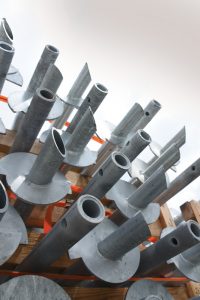
Structural Steel H-Piles
The design and detailing of H-piles must now conform with requirements of AISC 341, Seismic Provisions for Structural Steel Buildings, for a structure assigned to Seismic Design Category D, E, or F.
1810.3.5.3.1 Structural steel H-piles. Sections of structural steel H-piles shall comply with the requirements for HP shapes in ASTM A6, or the following:
-
- The flange projections shall not exceed 14 times the minimum thickness of metal in either the flange or the web and the flange widths shall be not less than 80 percent of the depth of the section.
- The nominal depth in the direction of the web shall be not less than 8 inches.
- Flanges and web shall have a minimum nominal thickness of 3⁄8 inch.
For structures assigned to Seismic Design Category D, E, or F, design and detailing of H-piles shall also conform to the requirements of AISC 341.
Change Significance: Steel H-piles (Figure 3) used in higher seismic design categories are expected to yield just under the pile cap or foundation from a combined bending and axial load. Design and detailing requirements for H-piles in AISC 341 are intended to produce stable plastic hinge formation in the piles. A plastic hinge is the area along the pile length that yields or stretches with permanent deformation during an earthquake.
Because piles can be subjected to tension caused by overturning moment during an earthquake, mechanical means to transfer the tension to the pile cap must be designed for the required tension force and not less than ten percent of the pile compression capacity. This requirement focuses on the attachment of a pile to the pile cap with enough strength in the connection that the pile steel will not pull out of the pile cap. See Section 1810.3.11 for more information on changes to the pile cap requirements.
Piles located in site class E or F soils – poor, liquifiable, and expansive soils – must satisfy the requirements for moderately ductile members per AISC 341.
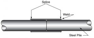
Deep Foundation Element Splicing
Deep foundation element splices for buildings in Seismic Design Category A and B regions designed by general engineering practices do not have to meet the 50 percent tension and bending capacity requirements.
1810.3.6 Splices. Splices shall be constructed so as to provide and maintain true alignment and position of the component parts of the deep foundation element during installation and subsequent thereto and shall be designed to resist the axial and shear forces and moments occurring at the location of the splice during driving and for design load combinations. Where deep foundation elements of the same type are being spliced, splices shall develop not less than 50 percent of the bending strength of the weaker section. Where deep foundation elements of different materials or different types are being spliced, splices shall develop the full compressive strength and not less than 50 percent of the tension and bending strength of the weaker section. Where structural steel cores are to be spliced, the ends shall be milled or ground to provide full contact and shall be full-depth welded.
Exception: For buildings assigned to Seismic Design Category A or B, splices need not comply with the 50 percent tension and bending strength requirements where justified by supporting data.
{remainder unchanged}
Change Significance: Steel pile splices (Figure 4) must be designed to resist axial and shear forces as well as moments occurring at a splice location. Conformance with this requirement ensures the structural integrity of the splice. Section 1810.3.6.1 contains restrictive splice requirements for structures assigned to Seismic Design Categories C through F. For low seismic areas, commonly available splices are acceptable in many design situations, such as a splice located deep enough that significant tension or bending demands are not expected or possible. Load requirements at the splice diminish due to soil resistance above the splice when the splice is located at depth.
Splices in low seismic design categories are exempt from having to be designed to fifty percent of the tension and bending strength of the pile material. For example, if friction piles are driven to 240 feet, the splice between the two 120-foot sections is 120 feet below grade. These piles do not need to be checked for a capacity of fifty percent of the pile tension and bending capacity. The pile is braced at the splice by surrounding soil.
All other requirements of Section 1810.3.6 continue to apply for pile splices in areas assigned as Seismic Design Categories A and B.
Precast Concrete Piles
Precast concrete piles are now to be designed following ACI 318, Building Code Requirements for Structural Concrete, rather than IBC provisions.
1810.3.8 Precast concrete piles. Precast concrete piles shall be designed and detailed in accordance with Sections 1810.3.8.1 through 1810.3.8.3 ACI 318.
Exceptions:
-
- For precast prestressed piles in Seismic Design Category C, the minimum volumetric ratio of spirals or circular hoops required by Section 18.13.5.10.4 of ACI 318 shall not apply in cases where the design includes full consideration of load combinations specified in ASCE 7 Section 2.3.6 or Section 2.4.5 and the applicable overstrength factor, Ω0. In such cases, minimum transverse reinforcement shall be as specified in Section 13.4.5.6 of ACI 318.
- For precast prestressed piles in Seismic Design Categories D through F, the minimum volumetric ratio of spirals or circular hoops required by Section 18.13.5.10.5(c) of ACI 318 shall not apply in cases where the design includes full consideration of load combinations specified in ASCE 7 Section 2.3.6 or Section 2.4.5 and the applicable overstrength factor, Ω0. In such cases, minimum transverse reinforcement shall be as specified in Section 13.4.5.6 of ACI 318.
{Sections 1810.3.8.1 Reinforcement through 1810.3.8.3.4 Axial load limit in SDC D-F deleted without replacement}
Change Significance: Sections 1810.3.8.1 through 1810.3.8.3.4 of the IBC have been deleted as similar provisions are included in Chapter 18 of the 2019 edition of ACI 318. Two exceptions for precast prestressed piles (Figure 5) are retained in the 2021 IBC.

Exceptions 1 and 2 recognize that the volumetric ratio of spiral reinforcement need not be greater than that required for driving and handling stresses when a pile foundation system is designed for load combinations including overstrength. Increased axial forces, shear forces, and bending moments provide a significant factor of safety against nonlinear pile behavior when the design includes overstrength effects.
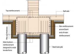
Pile Caps
Pile cap requirements have been updated to align with the 2019 edition of ACI 318.
1810.3.11.2 Seismic Design Categories D through F. For structures assigned to Seismic Design Category D, E, or F, deep foundation element resistance to uplift forces or rotational restraint shall be provided by anchorage into the pile cap, designed considering the combined effect of axial forces due to uplift and bending moments due to fixity to the pile cap. Anchorage shall develop not less than 25 percent of the strength of the element in tension. Anchorage into the pile cap shall comply with the following:
{No changes to Items 1 and 2}
3) The connection between the pile cap and the steel H-piles or unfilled steel pipe piles in structures assigned to Seismic Design Category D, E, or F shall be designed for a tensile force of not less than 10-percent of the pile compression capacity.
Exceptions:
-
-
- Connection tensile capacity need not exceed the strength required to resist seismic load effects including overstrength of ASCE 7 Section 12.4.3 or 12.14.3.2.
- Connections need not be provided where the foundation or supported structure does not rely on the tensile capacity of the piles for stability under the design seismic force.
-
{remainder unchanged}
Change Significance: Steel piles used in higher seismic design categories are expected to yield just under the pile cap
(Figure 6) or foundation because of combined bending and axial load. Design and detailing requirements of AISC 341 for H-piles are intended to produce stable plastic hinge formation in steel piles. Because piles can be subjected to tension caused by overturning moment, mechanical means to transfer such tension must be designed for the required tension force, but not less than 10-percent of pile compression capacity.
Conclusion
Structural engineers should be aware of significant structural changes that have occurred in the 2021 IBC. Frost protection for egress doors has been added to the foundation requirements. Calculation of the allowable axial design load for helical piles has been clarified. The design and detailing of H-piles must now conform with AISC 341 requirements for a structure assigned to Seismic Design Category D, E, or F. Deep foundation element splices for buildings in Seismic Design Category A and B regions designed by general engineering practices do not have to meet the 50 percent tension and bending capacity requirements. Precast concrete piles are now to be designed following ACI 318 rather than IBC provisions. Pile cap requirements have also been updated to align with the 2019 edition of ACI 318.■