
Part 4: Structural Investigations
This four-part series discusses the adaptive reuse of the Witherspoon Building in Philadelphia, PA (Part 1, STRUCTURE, September 2021, Part 2, October 2021, Part 3, November 2021). Part 4 continues the discussion of the structural investigations, including the Gray columns, new floor openings, and demolition of the second-floor mezzanine to allow for a new second-floor loft. Numbered photos are provided in the print version of the articles; lettered photos are provided only within the online versions of the articles.
Structural Investigations
Gray Columns
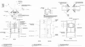
The configuration of the fabricated steel Gray column cross-sections involved four sets of vertical Carnegie Steel double angles located 90° from each other around the circumference of the section. These were connected to the adjacent angles via articulated, riveted gusset plates uniformly spaced vertically for the full height of the column. A total of four plates were located at each connection level (Figure 16).
Because of this unusual configuration, a finite element analysis (FEA) determined that the loads imposed on any one set of double angles by a beam reaction at any level would not be shared with any of the other three pairs of angles over the full height of the column. This condition occurred because of the inability of the riveted gussets to adequately transfer the vertical load of any one of the double angles to the other adjacent double angles. This situation, along with the findings of a weldability analysis conducted for the Gray columns, influenced the development and design of the connection of the new loft beams to these unusual existing columns.
Weldability
As indicated previously, it was assumed that the components of the Gray columns were rolled by Carnegie Steel; therefore, a chemical lab analysis of a sample from a steel beam obtained from the 9th floor was used to conduct a weldability analysis. From the findings of the lab test, a calculation of the carbon equivalency (CE) based on the Dearden-O’Neill Equation (from the American Welding Society (AWS) Guide for Strengthening and Repairing Existing Structures, D1.7) resulted in a CE value of 0.23% for steel with a carbon content greater than 0.12%. This value was significantly less than 0.35% (which would require that special care be taken when welding) and well within the recommended CE range provided in Table 6-1 of The Procedure Handbook of Arc Welding by the Lincoln Arc Welding Foundation. Therefore, the CE value for the beam sample indicated good weldability.
Based on the results of the above analysis, it was determined that the welding procedures, including any required preheating, could comply with the requirements of Section 4.5 of AWS D1.7. However, although the results of the weldability analysis indicated the Gray columns could be field welded, the results of the FEA concerning the inability of a Gray column to distribute the imposed vertical loads uniformly across the section influenced the design of the new loft beam connections. In addition, there was a real potential for material strength reduction at any one of the vertical double angles due to the heat generated by the welding process, which could weaken the angles and cause a localized failure unless the column was shored the full height of the building. As a result, all new beam connections were designed to connect only to the internal gusset plates.
In addition, an in-situ weld test, recommended by AISC Design Guide 21, Welded Connections – A Primer for Engineers, was also conducted at one of the top gussets at a Gray column that extended into the original mechanical penthouse and was therefore not supporting any appreciable vertical load. The test confirmed that the proposed welds associated with the new loft beam to Gray column connections did not damage the existing section.
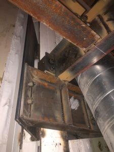
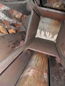
Typical 1st-floor loft beam connections to existing Gray column gusset plate details are shown in Figure P. Figures 17 and 18 show examples of the erected condition of the same beam-to-Gray-column connections.
New Floor Openings
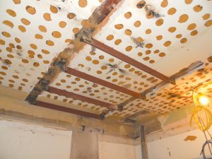
As previously noted, large trash chute and mechanical chase openings were required full height of the building above the 1st floor. An investigation was conducted to locate the existing concealed beam framing and individual tiles in the area of the building impacted by the openings to minimize the disruption and re-support requirements of the affected clay tile arch framing. The beams were located using handheld ground penetrating radar (GPR) as previously described. The individual tiles were located after the beam locations were established by removing strips of the plaster ceiling parallel to the beam span and perpendicular to the arch span.
Removing the plaster revealed the location and direction of the tile scoring and joints, which confirmed the assumed direction of the arch span and established the location of the joints between adjacent rows of tiles. Once the beam and tile row joints were determined, the locations of the new openings were established to minimize the need to reinforce the remaining tiles after the tiles within the footprint of the openings were removed. This was accomplished by locating the edges of the new openings at a joint between adjacent tile rows and at the end of an arch span corresponding to a supporting floor beam.
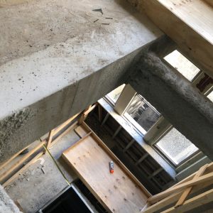
This approach avoided interrupting the arching action of any one row of tiles between the beam supports. Unfortunately, the contractor could not control the demolition at the openings well enough to avoid damaging the remaining row of tiles next to the opening. As a result, it was necessary to form and pour cast-in-place reinforced concrete beams between the supporting steel beams to provide adequate support of the remaining damaged tile arch sections at the edge of the openings (Figure 19).
Unfortunately, the investigation could not identify any of the anticipated tie rods typically located at the exterior arch span, which is where the new openings were to be located, next to an exterior wall. Typically, tie rods for flat-arched clay tile framing are not visible because they are generally located at least 3 inches from the bottom of the tile. As a result, it is challenging to locate the steel rods using a ferroscanning device such as a Profometer. In addition, it is also difficult to locate the rods using GPR due to the significant number of internal cavities associated with hollow clay tiles. The best method of locating tie rods is via the use of X-Rays. In-situ radiography can determine both the spacing and diameter of the rods without damaging the tiles. However, this method of non-destructive testing was not feasible for the project.
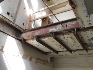
Absent tie rod location information, it was necessary to design supplemental ties, which consisted of steel angles located in the remaining arch span next to the openings that were welded to the bottom flange of the steel beams located at each end of the same arch span. These supplemental ties were required to resist the horizontal arch thrust force at the beam adjacent to the new openings without knowing the actual number of tie rods that would be damaged by the demolition of the tiles within the new openings. As a result, the new ties had to be installed before the demolition of the openings began (Figure 20).
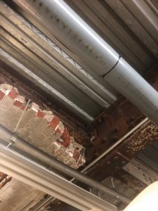
During the demolition process, the presence of tie rods was confirmed (Figure Q). The ¾-inch-diameter steel rods were spaced at approximately 5 feet on-center and located near mid-depth of the existing 12-inch-deep Carnegie Steel beams, which in turn were also spaced at approximately 5 feet on-center. A lab test of one of the rods removed from a new opening indicated a yield strength of approximately 50 ksi, which equates to a factor of safety of approximately 2.75 for the recommended maximum allowable stress of 18 ksi provided in the Principals of Tile Engineering Handbook of Design for the design of flat arch, hollow clay tile framing.
Utilizing the recommended formula and allowable stress for determining the load capacity of a hollow clay tile arch from the same reference resulted in a uniform load carrying capacity of approximately 280 psf. Deducting the existing topping weight and the tile and plaster ceiling resulted in a reserve load carrying capacity of approximately 170 psf, almost twice the reserve load-carrying capacity of 100 psf determined for the floor beams.
Additional Structural Renovations
In addition to previously described structural renovations, strengthening was required for several other areas of the building during the construction phase of the project.
9th Floor Beam Damage
While drilling new holes for plumbing waste lines, a subcontractor cored through the entire cross-section of an existing, 12-inch-deep, 9th-floor beam at the approximate midspan of the member. Although the beam did not deflect or exhibit any other indication of structural duress, the member was re-supported using two new steel channels that were underslung and straddled the damaged beam.
The new channels were connected by uniformly spaced stiffener plates attached to the bottom flange of the original floor beam to support the damaged section. The channels, in turn, spanned between the supporting girders via hanger connections. The fact that the clay tile arch supported by the damaged beam did not deflect, even though the span of the arch was essentially doubled, is a testimony to the resilience and extraordinary load-carrying capacity of this type of vintage framing system.
Demolished Existing 2nd Floor Mezzanine
After the existing 2nd-floor mezzanine was demolished for the proposed new 2nd-floor loft, which was eventually eliminated from the adaptive reuse project, it was necessary to strengthen the existing remaining two-story steel wide flange columns that remained and extended up to support the 1960s 3rd-floor infill framing above. In addition, several of the existing Gray columns in the same area of the building were also strengthened because it appeared that the same members at one time had been braced by framing that had existed within the Witherspoon Hall space but had been removed when the 2nd-floor mezzanine was constructed in the 1960s.
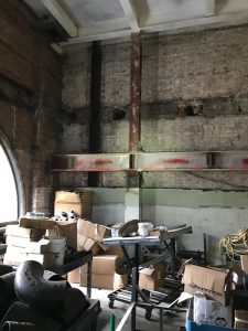
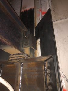
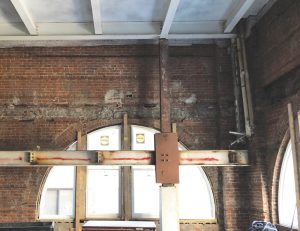
Horizontal, diagonal bracing was installed between the wide flange columns checked for the approximate two-story unbraced length and the existing Gray columns. Some of the wide flange columns had not been erected as a continuous vertical member at two 2nd floor mezzanine beam cantilevers. Instead, they had been interrupted by the same beams (Figure R). Reinforcing plates and stiffeners were installed to ensure the remaining stacked columns would behave as a continuous vertical member (Figure 21).
Existing 2nd Floor Roof Top Unit (RTU) Dunnage
Due to lack of space on the original mechanical penthouse roof for all of the new required RTUs, one of the units was placed on an existing exterior steel dunnage frame at the 2nd floor that had been previously used to support Liebert units for the old office spaces on the west side of the building at the courtyard area. The analysis and strengthening of the existing dunnage were performed by another structural engineer hired directly by the mechanical contractor. As the SEOR, the analysis, design, and calculations were peer-reviewed by Pennoni. In addition, the responsibility for ensuring that the existing building structure was capable of supporting the new RTU load and modified dunnage was assumed by the SEOR.
Assessment results associated with the existing supporting structure involved a considerable amount of investigation and exploratory demolition due to the complexity of the existing building below the 2nd floor in the vicinity of the dunnage in question. The investigation results indicated that the existing structure was adequate, including steel beams and a transfer girder over the mechanical sub-basement area that indirectly supported a portion of the dunnage above. However, at the existing 20-inch-deep Carnegie Steel B3 transfer girder, a splice in the beam near the midspan of the section was determined to be deficient for the new imposed loads (Figure 22). A new HSS steel column was installed between a new footing at the sub-basement slab and the bottom of the girder at the splice to reduce the span of the member.
Conclusions
The structural investigation, analysis, and design associated with the adaptive reuse of the historic Witherspoon Building were all challenging and interesting. In the absence of existing drawings, it was fascinating to discover the concealed aspects of the structure as the building revealed itself during the construction phase. From the author’s perspective, the most interesting aspects of the structure included the Gray columns and the 4th-floor transfer trusses.
The adaptive reuse of the building was also a sustainability success because, as Architect Carl Elefante stated in a 2007 National Trust for Historic Preservation Journal article, “…the greenest building is one that is already built…” The restoration of the building was also a historical success, which benefited the developer through the available tax credits associated with this type of project.■