
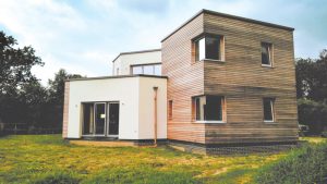
Pig Patch House is a single-family custom house located in England. It is built from mass timber panels used in the walls, upper floor, and roofs, suspended insulated precast concrete floor planks at ground floor level, and RC ground beams on mini concrete piles used as foundations.
There are two types of dowel laminated timber products that have been used in this project. The wall panels are made of timber planks aligned in three directions, a diagonal layer sandwiched between two (or four) orthogonal layers. The floor and roof panels are made of traditional dowel laminated timber, where planks are all installed in one direction.
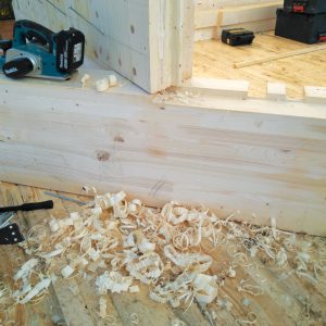
The mass timber panels used in the walls are made entirely from wood without any resin. In producing these panels, boards are laid on a mounting table in layers in three directions: longitudinal, diagonal, and transverse. Blind holes are drilled, and the solid wood threaded dowel is screwed in. The threaded dowels are made of well-dried and compressed beech. As they are inserted into softwood (spruce), they absorb the ambient humidity of the surrounding spruce board layers, swell up, and connect solidly with the surrounding wood.
The mass timber panels used in floors and roofs are made of timber planks/boards oriented in the same direction and connected with beech threaded dowels.
Pig Patch House is not a square house; it has an irregular shape at both levels. The ground floor is an open plan providing the dining and kitchen area directly over more than a half of the footprint, with some smaller rooms and upper floor stair access occupying the other half. On the upper floor, there are two bedrooms and a large roof terrace. Very few walls align at the two levels, which means that some areas have an upper floor structure spanning over 20 feet (6 meters). The external walls have large door and window openings up to 10 feet (3 meters) wide. All these factors presented design challenges.
The house is built in a rural area, surrounded by large mature trees and shrubs. The soil in this area is high plasticity clay, prone to shrinkage and heaving due to moisture variations caused by nearby trees. To address this, the foundation system is designed as reinforced concrete ground beams 24 inches wide (600 millimeters) by 18 inches deep (450 millimeters), spanning over 12-inch-diameter (300-millimeter) mini continuous flight auger piles installed at proximately 10 feet (3 meters) on-center.
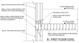
The ground beams support precast insulated prestressed concrete units, which are laid on top. Due to the presence of prestressing tendons, there are limited areas where resin anchors can penetrate the panels. As a result, the layout of the ground floor units was developed to suit the position of internal and external walls to allow fasteners for the timber wall cleats (plates) to be in this safe zone.
The stability of the building is derived from the external panels, and the horizontal forces are transferred into the walls at the ground floor level by diaphragm action of the upper-floor structure. The shear-center of the ground floor wall is positioned closer to the area with smaller rooms. This was addressed in the distribution of the forces that would need to be resisted by the walls. It is assumed that only external walls contribute to the stability of the building to allow for potential future adaptations.
The upper-floor structure is made of 4-foot-wide (1.2-meter) by max 36-foot-long (11-meter) dowel laminated timber panels. These panels transfer the load and are designed to span as one-way panels. Since the panels act independently, the connection between two adjacent panels was achieved with 11⁄32-inch-diameter (9-millimeter) screws installed at an angle of 45 degrees and a spacing of 8 inches (200 millimeters) along the junction. These screws allow the floor to act as a deep beam for the horizontal loads, transferring the horizontal loads into stability walls. A similar approach was adopted for the roof diaphragm.
To span over large door and window openings, panels above the upper floor have been designed as deep beams. As noted earlier, the wall panels are constructed from timber planks in lamellas that span in three directions (horizontal, vertical, and diagonal). The diagonal layer is required for the resistance of horizontal (racking) forces. Therefore, only the outer lamellas that run parallel to the opening could be used to bridge over the opening and transfer the load from the upper-floor structure onto the walls. It should be noted that the planks in the lamellas are only connected to other planks by beech dowels. Although the deep beam panel would have worked similarly to a traditional CLT deep beam, the designers assumed that each individual plank in the external lamellas would carry a portion of the total load applied on the deep beam panel. This load was estimated based on the stiffness of each of the planks.
This was a conservative approach because beech dowels will transfer the load from each of the planks in the external lamellas onto other lamellas and create a mass timber panel of similar properties to a traditional cross-laminated timber panel.
The deep beam over some of the windows also acts as a balustrade for the roof terrace. To achieve this, the cleat plate at the bottom had to be intermittent to allow direct transfer of moments and shear forces into the upper-floor structure through pairs of 11⁄32-inch-diameter (9-millimeter) screws installed at an angle of 45 degrees.
As mentioned above, the upper-floor structure had to span over 20 feet (6 meters) while carrying the load from the upper-floor walls supporting the roof and the upper-floor roof terrace. Because the upper-floor structure is only 6 inches thick (150 millimeters), a single glulam beam was installed over the upper floor and hidden within one of the walls to help transfer the loads. The glulam beam is connected to the floor panel with screws and load-shared between the two.
Fire design was an integral part of the project because most timber panels were left exposed as walls or soffits. The exposed timber, left untreated, did not satisfy prescriptive requirements from Approved Document B of BS 9991:2015, Fire Safety in the Design, Management and Use of Residential Buildings – Code of Practice, for flame-spread to satisfy the Building Regulations 2010 (UK). The Approved Documents mentioned above are prescriptive documents for fire safety design, which are analogous to the role building codes play in the U.S. They demonstrate to designers how to meet the minimum requirements for fire safety as mandated in the Building Regulations.
Approved Document B Fire Safety – Volume 1: Dwellings, 2019 edition, provide designers with an efficient means of meeting fire safety requirements for common building situations. However, they are not the only option available to design teams. The design team can deviate from the prescriptive guidance if they demonstrate that the building is still safe and meets the requirements of the Building Regulations. In the case of Pig Patch House, there was a desire to leave the timber panels untreated and fully exposed.
This was achieved using a performance-based approach. Understanding that the untreated timber has an increased rate of flame spread relative to a guidance-compliant solution and that this impacts the early stage of fire development, a mitigation strategy was developed which similarly addressed the early stage of the fire and improved occupant evacuation. Detection was increased throughout the house to alert occupants to a potential fire much sooner relative to a guidance-compliant solution with only a single detector in corridors.
The effectiveness of this mitigation strategy was quantified using fire modeling to determine how long it takes for conditions to become unsafe, evacuation calculations to determine an overall range of evacuation times for occupants, and an event tree analysis to quantify the risk of each scenario. This type of analysis can demonstrate that the holistic fire strategy achieved the required level of performance despite aspects not meeting prescriptive guidance.
This custom house has demonstrated that, by understanding the structural and fire safety nuances of mass timber construction, the material can be successfully applied to satisfy architectural and sustainability goals while meeting life safety requirements. The two-way nature of the Nur-Holz panel allowed for efficient structural framing, while the thoughtful introduction of glulam elements allowed for load transfers between the floors. It was also shown that a holistic fire safety strategy was able to quantify the performance of the mass timber building while creating design opportunities beyond prescriptive guidance.■