
Addressing Complexity in an Aircraft Hangar Lateral Load Resisting System
In answer to the growing demand for more commercial and defense aircraft, larger-scale maintenance hangar construction is on the rise. These projects are characterized by unobstructed service bays that span hundreds of feet, posing a structural challenge for which architects often specify a cantilevered steel frame.
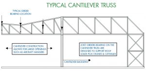
As conceptually shown in Figure 1, the size and complexity of a cantilevered hangar design can present a unique set of engineering challenges. The integration of massive steel trusses and other structural elements can increase project costs. However, steel joist girders, along with steel joists and decks, can offer a cost-effective solution. Steel joist companies are ready to meet these complex challenges, offering a combination of robust engineering knowledge and 3-D modeling tools.
Design, Detailing, and Fit-up
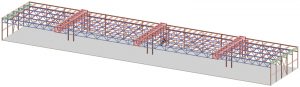
As shown in Figure 2, a hangar project calls for three cantilevered truss towers. The towers rise at the back side of the building and cantilever over the roof to the front of the hangar. Emanating from the truss towers is a load-resisting system consisting of joists and joist girders. The design establishes the desired open bay space, but it also requires a carefully engineered system that details a range of possible structural fit-up challenges.

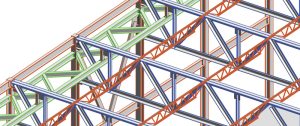
Figure 3 shows how, as the roof structure slopes to the back of the bay, the steel joists also slope. The joist girders must frame into the cantilever frame to form the roof slope. In addition, as shown in Figure 4, the slope of the hangar roof may require that a horizontal truss fit up with each supporting steel joist girder at varying connection points. A horizontal truss along the front of the bay must be designed for lateral wind and seismic loading. This truss must be detailed to fit with the joist girders and may even be designed to rest on the top chord of a supporting steel joist girder. As the horizontal truss slopes toward the back of the hangar, the joist girders that support the truss must fit up with the horizontal truss at varying connection points. This requires close collaboration between the structural steel engineer and the steel joist engineer to address varying load/force calculations with related bolting and bracing details.
Vertical and Lateral Loading
Girder deflection on large, open, cantilevered hangar bay designs is often subject to live load deflection limitations related to the movement of supported maintenance equipment and service personnel. The structural engineer (SEOR) may require deflection limits approaching L/700 to ensure the safe, smooth, and reliable operation of suspended cranes and overhead doors.
Accordingly, the joist manufacturer conducts loading analyses using the SEOR’s requirements to calculate the precise point loads at each brace, crane, and joist location. Each load case must be organized in tabular form and verified with the joist company’s design software. The manufacturer needs to check the accuracy of each loading calculation with a redundant review process to assure that, for each load case, the joist girder and truss act as one structure to deflect precisely under live load.
The manufacturer signs and seals the calculations as the delegated engineer and submits the calculation package to the SEOR for project review and approval to ensure overall design performance. The SEOR can also use this information from the manufacturer to present to the building official for code review. In addition to taking advantage of the joist manufacturer’s engineering expertise, the SEOR can also employ a peer-review process to ensure building performance and public safety.
Joist Girder Bearing
A joist girder with a depth of 10 feet and a span of up to 140 feet with significant vertical and lateral loads will have large end reactions (shear). Therefore, establishing adequate joist girder bearing is essential for proper fit-up and management of these reactions in a cantilevered frame system.
When fitting up the cantilever frame and a joist girder end panel, the joist engineer must give adequate seat clearance for the joist girder connection at the cantilever frame. For example, 12-inch-deep girder seats allow clearance for 8-inch top chord angles and provide the joist manufacturer the needed design flexibility. In addition, a minimum 12-inch seat length allows adequate space to use four 1-inch structural bolts for erection. This provision also supplies acceptable welds to resist high uplift reactions.
The joist engineer may experiment with the end web slope to change the end web size. A steep slope reduces the force in the web, but the bearing requirement must balance this. The joist engineer must check the eccentricity to minimize end moments while remaining aware of any required clearances with other structural elements. The 12-inch-deep seat helps with these considerations. The SEOR must be mindful of the potential for additional moments due to eccentricity as they consider these connections.
The SEOR may also use the joist girders as part of the lateral load resisting system. As such, the joist engineer must check the girder top chord and seats for these axial forces. The SEOR may also utilize large horizontal trusses to manage large lateral loads, which may be present in high wind or seismic regions. These trusses may interact with the girders creating challenges for detailing and field erection. The steel and joist detailers can work together using 3-D modeling to tighten clearances to acceptable shop and field tolerances.
Field-bolted Splices
Steel joist girders specified for hangars, along with cantilever frames, can achieve hangar openings up to 450 feet or more. At these spans, joist girders typically require field-bolted splices depending upon shipping and site limitations. However, the location of a midpoint splice for a given joist girder may not work when considering the large loads that are characteristic of a cantilevered hangar structure. When designing the girder bottom chord splice for maximum gravity tension and the top chord splice for maximum uplift tension, the capacity of the splice may not be sufficient. Moving the splice locations to the third points reduces the required tension force. A further tactic may be to increase the tension capacity of the top chord splice by utilizing a similar splice design generally used on the bottom chord. But these splices typically have a plate on the top chord, affecting fit-up at the joist bearing locations.
Experience dictates that while these tactics can address large splice forces, they can also introduce complications due to changes in the steel joist girder geometry, affecting the horizontal truss, crane brace, and overhead door brace clearance. The joist manufacturer, along with the steel supplier, can check proper clearances by using 3-D modeling. This solution may require adjustments to joist girder geometry, splice, and brace locations to assure that the splice locations do not foul with crane and brace load locations while maintaining an efficient girder design.
Similarly, modeling the joist seat depths and splice locations can guide the adjustment of the joist seat depths to ensure sufficient clearance for the attachment of the joists to the joist girders at the splice locations. The joist manufacturer and the structural steel detailer must coordinate joist seat depth to provide adequate bearing and clearance for the joist seats. In addition, the joist manufacturer must ensure that joist seats do not interfere with the field fit-up of the bolted splices.
Project Coordination
For project success, the structural steel supplier must closely coordinate with the joist manufacturer, the SEOR, and the steel erector to ensure ease of design and erection. Early in the project, the structural steel supplier should choose a joist manufacturer experienced with the complexities associated with open bay construction. The joist manufacturer’s early involvement ensures enough lead time to produce the required calculations and a 3-D model for approval by the SEOR.
The SEOR must provide detailed load diagrams, including all dead, roof live, crane, wind, and seismic loads to the joist manufacturer. They also need to supply serviceability requirements such as maximum deflection under live loads, including cranes and catwalks. In addition, they must consider camber which can be excessive at longer spans. See SJI technical digest #9 and 45th edition Standard Specifications for more information regarding camber.
The SEOR needs to review the joist manufacturer’s submittal to ensure building performance. On these complicated projects, the SEOR may delegate the design of the steel connections to another engineer. In many cases, the steel supplier contracts with this delegated engineer and coordinates the connection design between the SEOR, the joist manufacturer, and the connections engineer.
Summary
Owners and architects can create massively open and unobstructed aircraft hangar bays by leveraging the unique advantages of the cantilevered frame system paired with joists, joist girders, and deck supplied by an experienced manufacturer. These projects will be high-flying successes when the SEOR is supported early by an experienced team of engineers representing both the structural steel supplier and the steel joist manufacturer. Early coordination utilizing 3-D modeling will eliminate costly field errors, saving money and time for the owner.■
Working the Angles
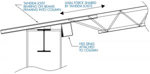
A recent cantilevered bay project called for the steel joists to have sloped baseplates designed to support up to 50-kip seismic axial load (Figure 5). The SEOR determined that the most efficient approach was to create an HSS drag to transfer the axial force through two joists back to the lateral resisting system. This HSS was not used for bearing, which created eccentricity, increasing the design moment induced by the axial force plus eccentric bearing. Since the joist bears on the W-section, not on the HSS, the joist seat was designed for eccentric bearing plus a 25-kip axial transfer. The solution introduced complexities to fabrication but allowed this rather large axial force to be transferred through the joist top chord. As can be seen in this example, modern steel joist manufacturers can provide flexible and efficient solutions for complex projects.