
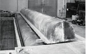
The Texas Department of Transportation (TxDOT) employs various concrete bridge superstructure options depending on span length, traffic, and future crossing requirements. Among these, pan-girders were a popular choice in the 1950s and 1960s as a viable alternative for short-span bridges due to their speed of construction, low labor requirements, and cost-effectiveness. The name “pan-girder” came from the pan-shaped formwork that was used in construction. The formwork consisted of an upper semi-circular cross-section with straight ends on the bottom of each side (Figure 1). Pan-girder bridges were cast using self-supporting metal forms that spanned between bent caps. Multiple pans could be placed next to each other to form a concrete web. They were connected with bolts that passed through holes on the sides of the forms (Breña, 2001). The pan forms supported the dead weight of the reinforcement and wet concrete, thus eliminating the need for shoring and falsework.
There are about 4,000 pan-girder bridges still in service in Texas, mainly designed for AASHTO live load designations of H10, H15, H20, HS15, and HS20 trucks. Even though they were originally designed for lesser loads, many pan-girder standards rated out at acceptable levels for HL-93 loading. The standards designed using the lightest AASHTO design loads (H-10 and some H-15) usually did not have an acceptable load rating at the HL-93 level. The decline in the use of pan girders occurred prior to the introduction of the HL-93 design load. Over time, pan-girder construction became labor-intensive, with much time dedicated to tying reinforcing and placing concrete in the pan forms. As the precast industry expanded in Texas, the cast-in-place bridge superstructure types fell out of favor due to economic reasons. With the advent of the heavier current AASHTO HL-93 design load (AASHTO 2011), the use of pan-girder bridges declined even more.
Due to a large number of these types of bridges, pan-girder bridges have been investigated for overall safety assessment and rehabilitation using external composite laminates. Because the bridge pans were not perfectly straight, fresh concrete could flow through gaps between adjacent forms during casting, leaving an irregular surface on the bridge webs. While this irregularity had no impact on the bridge performance, it can influence the placement of composites used to strengthen the bridges. This means composites could not be placed in the middle of the web without first doing some significant surface preparation, increasing labor cost and construction time (Breña, 2001).
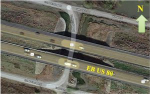
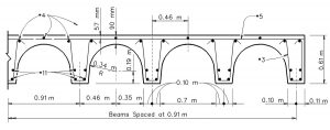
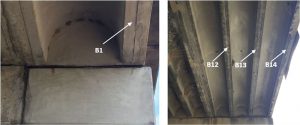
For the study discussed here, an in-situ evaluation was conducted of the East Bound (EB) US 80 pan-girder bridge (Figure 2) over a frontage road in Forney, Texas, through visual inspection and condition assessment. TxDOT recommended the inspections to catalog the current bridge condition in order to undertake future load rating and any strengthening that could be necessary. It is a 10 span and 252-foot-long bridge constructed in 1955. At each bent, there exist three separate bent caps. The first, second, and third bent caps support one, 10, and 3 beams, respectively. The bridge was widened in 1978 when one beam (Beam 1) was added to the north and three beams (Beams 12, 13, and 14) were added to the south of the existing bridge. Figure 3 shows the typical detail along the transverse section of the bridge.
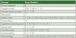
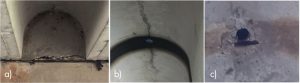
A detailed visual inspection plan was prepared, and the structural elements were evaluated for visible signs of distress, damage, and deterioration. Various types and levels of damage that could jeopardize the overall health and serviceability of the bridge’s structural elements were located and cataloged. Deteriorations included, but were not limited to, hairline cracks, concrete crushing and spalling, and water damage. Observed damages are summarized in the Table. Beam numbers are progressive from north to south. Identical beams in various spans showed similar levels and types of damage, and these repetitive damaged numbers of beams are shown in parenthesis after the corresponding beam numbers. For example, 3(2) indicates that beam number three in two spans showed an identical type of damage. In addition, it is apparent that most beams sustained some form of water damage at mid-span, as shown in Figure 4.
The presence of form lowering holes at the crest of the pan girders at quarter-span and mid-span of the girders could be the reason for water damage, as the water seeped through the holes. Efflorescence was visible in the form of white and gray residue, which occurs when the calcium salts from concrete react with water and air to form insoluble calcium carbonate. This phenomenon is harmful to concrete as salt can increase concrete permeability and induce corrosion of steel rebars. Corrosion propagated from the drainage areas in most of the girders, and a few beams had exposed rebars. Rebars were exposed and corroded in some of the beams around the form lowering holes. Such corrosion could occur due to the water seepage from the holes, which caused concrete scaling and spalling. However, no corrosion was observed in the primary longitudinal reinforcement, located at the bottom of the stem. If present, corrosion in the rebar could potentially affect the load-carrying capacity of the beams.
It may be noted that beams 1, 12, 13, and 14 displayed little or no water damage. These beams were added in 1978 during the bridge expansion, while the other beams were in service for about 23 additional years. The four newer beams were in much better shape and did not show any extensive visible deterioration and/or water damage (Figure 5). The new bent caps used for the widening were connected to the existing bent caps with dowel bars for continuity.
Beam 11 was the most severely damaged in all spans, with practically all the deterioration mentioned in the Table. Water damage was visible in this beam at every quarter-span location in all spans. Samples of deterioration are shown in Figure 6. This could be caused by the fact that Beam 11 was on the exterior side before the bridge widening; after widening, it became an interior beam that increased the load it carried and aided in the damage process.
The following recommendations, which can be applied to this and other pan-girder bridges, were made based on findings of the field inspection:
- A PVC pipe can be glued on the form lowering holes extending beyond the concrete surface of the arch. This will prevent water seepage through the holes and minimize water damage, spalling, and scaling of concrete.
- Pan-girder bridges were usually designed for a load lighter than the current AASHTO HL-93 live load requirement. Therefore, it is recommended that appropriate load testing, load rating, and analyses be undertaken for such bridges, especially older ones with significant deterioration, to verify the load-carrying capacity and adequate structural safety.
- Appropriate retrofitting and repair techniques may be used to upgrade deficient pan-girder bridges with extensive deterioration. For example, experience has shown that externally bonded Carbon Fiber Reinforced Polymer (CFRP) laminate is a viable method for strengthening concrete bridges in general (Mohanamurthy and Yazdani, 2015; Pallempati et al., 2016) and also for under-capacity pan-girder bridges. Thus, such rehabilitation methods may be suitable to upgrade deficient pan-girder bridges.
In conclusion, the study conducted herein showcased common deteriorations and distresses in a typical pan-girder bridge. The results indicate it is essential to conduct a detailed visual inspection on similar bridges to understand their current condition and undertake strengthening if they are deemed to be unsafe.■
References
AASHTO LRFD (2011) Bridge Design Specifications, Customary U.S. Units, 7th Edition. American Association of State Highway and Transportation Officials.
Breña, S., Wood, S. and Kreger, M. (2001) Increasing Flexural Capacity of Typical Reinforced Concrete Bridges in Texas Using Carbon Fiber Reinforced Polymers. The University of Texas Library. US Department of Transportation and Federal Highway Administration.
Google. (2018). www.google.com (Dec. 8, 2018)
Mohanamurthy, M., and Yazdani, N. (2015) Flexural Strength Prediction in FRP Strengthened Concrete Bridge Girders. Eur. J. Adv. Eng. Technol., 2(3), pp. 59–68.
Pallempati, H., Beneberu, E., Yazdani, N., and Patel, S. (2016) Condition Assessment of Fiber-Reinforced Polymer Strengthening of Concrete Bridge Components. J. Perform. Constr. Facil., 10.1061/(ASCE)CF.1943 -5509.0000902, 04016052.
Texas Department of Transportation (TxDOT, 1997) Bridge Inventory, Inspection, and Appraisal Program (BRINSAP) Database.