
Part 2: Adaptive Reuse and Structural Investigations
This four-part series discusses the adaptive reuse of the Witherspoon Building in Philadelphia, PA (Part 1, STRUCTURE , September 2021). Part 2 includes a discussion of the ongoing adaptations during construction and the structural investigations conducted to better understand the existing structure. Numbered photos are provided in the print version of the articles; lettered photos are provided only within the online versions of the articles.
Adaptive Reuse
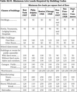
This adaptive reuse project primarily involved the conversion of an office building to residential units. The Architect of Record for the project was Deidre DeAscanis, AIA, with JKRP Architects, Philadelphia, PA. Initially, the difference between the minimum required live load capacity for the upper floors of Philadelphia office buildings in the early 20th century (60 psf) as documented in the 14th Edition of the Architects’ and Builders’ Handbook by Frank E. Kidder (Figure 6) and the current-day live load required for residential areas (40 psf) were utilized to allow for a 20 psf reserve load-carrying capacity at the upper floor levels.
Fifteen psf of the reserve load-carrying capacity was dedicated to partition dead loads required by the current governing building code. The remaining 5 psf was dedicated for miscellaneous loads such as ceilings, mechanical, electrical, and plumbing dead loads. However, based on the results of an investigation of the 5th and 11th-floor framing, it was determined that the actual capacity of the typical floor beam framing was 100 psf, which provided even more reserve load-carrying capacity than that indicated by the comparison of the building codes. In addition, earlier references similar to the Architects’ and Builders’ Handbook from the late 19th century indicate that the minimum live load for all floors of an office building in Philadelphia was 100 psf.
The minimum required live load capacity for the first floor of Philadelphia office buildings in the late 19th and early 20th centuries (100 psf), as documented in the Architects’ and Builders’ Handbook, was used for the evaluation of the adaptive reuse of the first floor, which included retail space, the main entrance lobby, and residential areas. At the residential areas of the first floor, new loft areas were made accessible from the first-floor residential spaces below. At these same areas, the combined loading of two occupied levels of 80 psf live load and 40 psf dead load (not including the dead load of the new loft floor framing and access stairs), for a total of 120 psf, exceeded the assumed existing 100 psf capacity of the first floor. This same assumed 100 psf load-carrying capacity established by the code research was also subsequently confirmed via the existing 1st-floor framing investigation.
As a result, independently supported loft floor framing was designed using ¾-inch Structural Panel concrete subflooring manufactured by USG. The subflooring spanned between cold-formed steel (CFS) joists supported by new wide flange steel beams that spanned between the existing Gray building columns. The 5% maximum gravity load increase allowed by the International Existing Building Code (IEBC) was used to justify the additional mezzanine loads imposed on the existing columns. Similarly, proposed loft areas associated with the 2nd-floor residential areas had to also be supported by new steel beams spanning between the existing building columns. This is because the assumed existing 100 psf capacity of the second floor was less than the anticipated combined loads of the same multi-level residential areas. However, this aspect of the adaptive reuse plan was not constructed due to limited headroom at the 2nd floor.
The original adaptive reuse plan also included constructing a new rooftop deck assembly area and related enclosed elevator lobby and separate stair access areas. It was anticipated that new, exposed steel rooftop dunnage framing would span between the existing main building columns, as required to provide the minimum assembly live load capacity of 100 psf. In addition, new stair and elevator penthouses were required to provide access from the 11th floor. However, the new rooftop features were excluded from the project due to the excessive cost of the proposed renovations.
Additional adaptive reuse features that impacted the existing structure included a new trash chute and mechanical chase from the 2nd to the 11th floor. In addition, the new mechanical chase extended up through the 11th-floor attic and roof framing. Due to the susceptibility of flat, hollow clay tile construction to penetrations, it was anticipated that these large new openings would involve re-support of the affected arch framing. Also, it was anticipated that the interruption of any existing tie rods used as part of flat arch tile construction that occurred within the new openings would require that the adjacent affected interior arch spans be strengthened.
For reasons similar to that described above for the new floor and roof openings, it was anticipated that smaller utility holes required for the new residential bathrooms and kitchens could potentially also require strengthening of the flat, tile arch construction. However, it was expected that the strengthening, as long as a tie rod was not interrupted, would only involve installing small steel compression frames that would enable the continuity of the surrounding flat arch clay tile units at the new penetrations (Figure F).
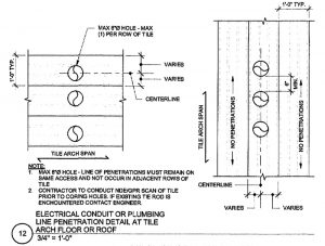
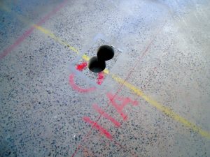
In addition, it was anticipated that penetrations that only involved small, cored holes would be allowed without reinforcing the tile if the penetrations could be located to minimize damage to the affected individual tile (Figure G). At similar existing holes that were no longer needed, the opening and surrounding cavities of the affected hollow clay tiles were simply infilled with lightweight concrete.
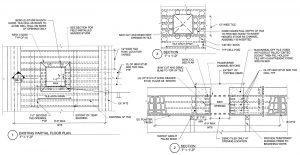
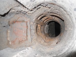
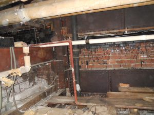
Lastly, it was also anticipated that infilling the large existing opening in the floors associated with the mechanical penthouse shaft (Figure 7),
added during the life of the building, would be required. This was accomplished by constructing new concrete slabs on metal deck that were supported by new steel beams spanning between the existing floor beams. The capacity of the existing steel beams around the perimeter of the openings to support the new dead and live loads associated with the infill framing was also confirmed.
Structural Investigations
As a part of the initial project design and ongoing adaptive reuse construction during the project, several investigations were conducted to better understand the existing structure without any existing drawings. A summary of the major investigations completed is provided below.
1st, 5th, and 11th Floor Framing
Investigations of the typical floor framing at the 1st, 5th, and 11th floors were conducted to confirm the load-carrying capacity of the existing Carnegie steel beams. The investigations concentrated on the steel beams rather than the hollow clay tiles because of the difficulty and cost associated with locating and measuring the tie rods used with this type of masonry flat arch framing, which is the most accurate method of estimating the load-carrying capacity of this same framing system. In addition, it is common for the load-carrying capacity of a flat tile arch to significantly exceed that of the supporting beams because of the large safety factors utilized by the original designers for this type of system.
The investigation of the beams at the referenced floors was conducted in the following manner. Because the beams were concealed by the existing floor finishes and the plaster ceiling, it was necessary first to locate the beams via handheld ground penetrating radar (GPR). In addition, because of the presence of an existing ±5-inch-thick concrete topping, which also included embedded conduits, it was necessary to scan the beams with the GPR from the ceiling side of the framing where only a few inches of plaster and solid tile separated the steel beam flange from the exposed soffit.
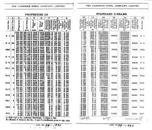
Once the beams were located and the centerline of the members was accurately marked on the top of the finished floor, the slab was then cored directly on top of the wide flange section to reveal the beam width. A second core was then taken through the entire depth of the topping and tile immediately adjacent to the flange tip of the beam to confirm the beam depth (Figures 8 and 9). Both of the core locations allowed the dimensions of the steel section to be accurately recorded and the thickness of the concrete topping, hollow clay tile, and plaster ceiling to be documented. It was not necessary to confirm the thickness of the tapered I beam flanges because the available Carnegie Steel section property tables (Figure H) only included dimensions for the beam depth and flange width and not the variable flange thickness.
The reserve load-carrying capacity of the floor beams at all three levels was determined to be approximately 100 psf based on the yield strength of the Carnegie beams documented as a part of the Main Roof and Original Mechanical Penthouse investigation described below.
Main Roof and Original Mechanical Penthouse
As indicated above, the original adaptive reuse plan for the building included constructing an open-air rooftop assembly space and a new access elevator and stair from the 11th floor for use by the residents. As a result, it was necessary to conduct a structural investigation to determine the load-carrying capacity of the affected roof framing.
As previously described, due to the termination of the interior building columns at the 11th floor at the north end of the building, existing fabricated steel roof trusses clear spanned between the main east and west sides of the building to support the main roof, original rooftop mechanical penthouse high roof and floor, and the 11th-floor ceiling framing. Therefore, the intent of the investigation involved determining the reserve load-carrying capacity of a typical steel roof truss, high penthouse roof steel purlin and beam, and main roof steel beam.
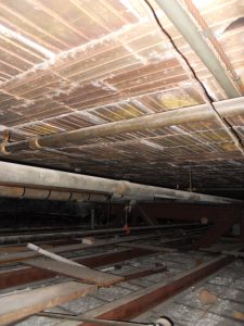
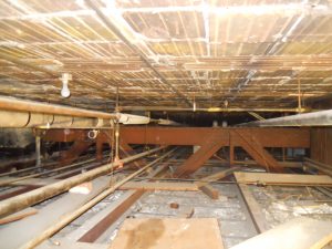
The findings of the investigation are provided below and were based on the results of a steel coupon test of a penthouse roof purlin that indicated an approximate yield strength of 32 ksi. The sample was taken from a portion of the bottom flange at the end of the span next to a supporting column. In addition, the location of the main roof beams and the direction of span of both the beams and tile arch were visible from the 11th-floor attic framing because plaster had not been applied to the tile soffit. As a result, the scored bottoms of the 12-inch-wide by 9-inch-long (in the direction of the arch span) hollow clay tiles were visible, with the beam locations identified by the scored bottoms of the end voussoir and beam soffit tiles arranged parallel to and centered about the entire beam span (Figure 10).

Similarly, because the soffit of the high penthouse roof had not been plastered, the location and direction of span of book tiles, bulb tees, purlins, and beams were also readily apparent. In addition, full-depth cores were taken at both the high penthouse and main roofs to confirm the thickness of the 4-inch book tiles (Figure 11) and 12-inch-depth hollow clay tiles, respectfully, and the associated existing roofing.
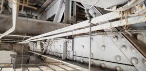
As indicated in Part 1 of this article, the southern portion of the main roof was not framed with trusses and instead was constructed with Carnegie Steel B Beams and built-up, riveted steel plate and angle girders as shown in Figure 12. This area of the building was subsequently investigated as a part of the Mechanical Penthouse and Cooling Tower Dunnage investigation that will be provided in Part 3 of the article.
High Mechanical Penthouse Roof Framing
The analysis of the exposed high roof steel beams indicated that the framing had a reserve load carrying capacity of approximately 50 psf in addition to the current-day code-minimum flat roof snow load. This maximum load was based on the capacity of the beams; however, the purlins had a reserve load-carrying capacity of approximately 75 psf. Therefore, a determination of the load-carrying capacity of the book tiles and supporting bulb tees was not performed.
Main Roof Framing
Only the 10-inch-deep north-south support beam along the east wall of the mechanical penthouse could be measured and therefore analyzed. The results of this analysis indicated that the member only had a reserve load carrying capacity of approximately 10 psf in addition to the current day code minimum flat roof live load, including snow drift loads.
Typical Roof Truss
The results of the analysis of a typical Warren roof truss (Figure I and J) indicated that the member did not have reserve capacity to support the proposed new rooftop assembly space deck; however, it did have adequate capacity to support the reserve capacities noted above for the penthouse high and main roof framing.
Part 3 of this series includes a continuation of the structural investigation, specifically regarding the main roof and original mechanical penthouse.■