
Use of CBFEM for Validation
Have you ever stopped for a second and thought, “do we ever validate our rigid plate assumption when designing anchorage to concrete?” The answer is simple. There is no analytical method for validation and, because the design codes mandate it, the design engineer abides by it as it is a Building and Safety (Plan check) requirement. This article demonstrates how Component Based Finite Element Modeling (CBFEM) can validate any base plate behavior, rigid or non-rigid. So, regardless of what base plate assumption you make as a design professional, now you can get validation.
Design of anchorage per the American Concrete Institute’s Building Code Requirements for Structural Concrete (ACI 318) is mandatory for structural engineers and design professionals in general. When discussing anchorage to concrete, a non-rigid plate assumption is a rarity, predominantly because the anchorage design codes mandate that the anchor forces be determined based on a rigid plate assumption. In a previous article (Morgan and Shahdin, Structural Analysis, STRUCTURE, January 2020), this and other consequences of non-rigid plate assumptions such as increased anchor forces were discussed. CBFEM as a methodology to analyze the non-rigid plate behavior was also discussed, and the Bi-Linear Stress-Strain curve was introduced to depict the behavior of the two-dimensional (2-D) shell elements of the plate. The article closed by highlighting some key CBFEM parameters that would help a structural engineer make an engineering judgment as to whether it is ok to go ahead with the non-rigid plate-based anchor forces for anchorage design.
The purpose of this article is to further the understanding of non-rigid base plate design by:
- Developing a non-rigid base plate criterion
- Linking the (above) criterion with previously explained CBFEM parameters
- Using the criterion to define a “Non-Rigid base plate Close-To-Rigid”
- Understanding the power of CBFEM methodology for validating rigid or non-rigid base plate assumptions
Non-Rigid Base Plate Design
A criterion for Non-Rigid Base plate assumption must first be developed. When a design engineer thinks about a non-rigid base plate, what comes to mind first? For instance, some say “a thin plate,” so thickness can be the first assumption. But then, very quickly, it is concluded that “thickness of the plate” itself does not entirely paint the picture until plate loading is examined. Furthermore, since Finite Element Analysis (FEA) is the common computational approach, the stiffness and material type of the profile/fixture is also a key ingredient to obtain a realistic load transfer. Finally, do not forget the anchors. In reality, the anchor types, sizes, and positions can also influence the load transfer and be considered input to a criterion.
To recap from the previous article, CBFEM methodology helps the design professional make an engineered decision on whether or not to accept the resultant anchor forces from a non-rigid plate assumption and proceed with an ACI anchorage design. This premise was developed on the three parameters.
Plastic Strain Limit
The plastic strain limit depicts the behavior of the plate beyond the yield point. To understand this further, look at the defined material behavior curve. A material behavior curve is typically a stress-strain curve that determines the behavior of the steel elements. In this case, the elements of choice for the plate are 2-D shell elements, and a bi-linear stress-strain curve is the material behavior curve of choice. A bi-linear stress-strain curve eases the understanding of material behavior. The behavior remains linear after yield, with a slight slope associated with it, as shown in Figure 1.
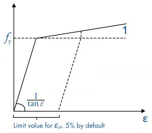
Until yield strength is reached, the plastic strain remains zero. This shows classic linear elastic behavior as defined by the American Institute of Steel Construction (AISC). Once the yield point is reached, the plastic strain counter starts. Now connect this parameter to the non-rigid plate criterion that was established above. In conjunction with the bi-linear stress-strain curve, the plastic strain limit percentage helps to understand the force level on the structure by relating it to the von Mises stress. The von Mises stress criterion is used to depict whether a given material will yield or fracture. Per this criterion, the material is assumed to be elastic before reaching the yield stress, Fy. CBFEM provides the stress (von Mises) related to a particular plastic strain limit, which can also be seen as an account of the loads applied on the plate. Therefore, it can be deduced that the plastic strain limit parameter relates to the loads on the plate.
Absolute Plate Deflection
Now the second parameter is examined to see how it can be related to the established criterion. As the plate yields, it deforms, and the CBFEM captures that absolute deformation. This closely relates to the first criterion for a non-rigid plate, i.e., “thickness of the plate.” A thinner plate would ideally deform more than a thicker plate and vice versa. So, it can be concluded that the CBFEM parameters (relating to the plate itself) that help us decide whether or not to use the non-rigid anchor forces for anchorage design, in fact, relate to the simple but logical criterion initially set.
Anchor Forces
The third parameter, an important one, is the anchor force. In CBFEM, as discussed in the previous article, the fixture, plate, and anchors are modeled as components held together by the mesh. Now, look at the load path through this model. The base plate receives the load from the fixture (column) and distributes it to the anchors. The load transfer in any CBFEM model is through the material stiffness and, hence, anchor stiffness plays a key role in the analysis. Since the non-rigid plate tends to yield, this methodology/assumption can help model the effects of prying action in the anchorage design. However, as a consequence, higher anchor forces should be expected compared to what would be expected from a rigid plate assumption. Therefore, the CBFEM methodology compares non-rigid anchor forces and equivalent rigid anchor forces to monitor the increase in the anchor forces that are determined as a consequence of assuming a non-rigid plate.
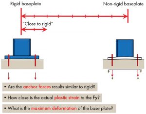
CBFEM methodology assumes the plate as non-rigid. However, the advantage of CBFEM is that, once the rigid plate behavior is validated, it is no longer necessary to use the higher anchor forces resulting from the non-rigid plate assumption. In that case, the forces obtained from any rigid analysis can be utilized. Therefore, using the above-developed criterion for a non-rigid plate and the associated (three) CBFEM parameters, a non -rigid plate can now be defined as “Close-to-Rigid.” This is illustrated in Figure 2.
A Design Example
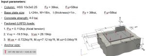
The following design example illustrates how it all comes together and how the CBFEM helps validate rigid/non-rigid plate behavior. Start with a fixture and loading criteria, as shown in Figure 3.
Validation of the Rigid Plate Behavior
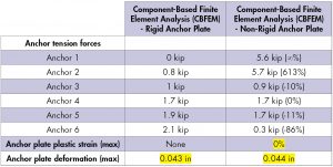
In the first part of the design example, run this fixture as is, i.e., given a one-inch-thick plate. Table 1 shows the results of the CBFEM.
Interpretation of Results:
a) Higher anchor forces as expected with a non-rigid assumption via CBFEM.
b) % Plastic strain limit is zero. This indicates that the yield stress, Fy, has not been reached on the bi-linear stress-strain curve. That depicts a rigid plate behavior. However, this can be further proved by looking at the von Mises stress calculated by CBFEM. That value is around 18 kips per square inch (ksi), which shows that, load-wise, the results fall about halfway on the linear portion of the curve below Fy. This is classic linear elastic behavior.
c) Absolute deflection for the non-rigid case is precisely the same as that of the rigid case.
d) Summarizing the results from the parameters above, this is a true rigid plate behavior, even though it has been analyzed using CBFEM. This is how CBFEM methodology can be used to validate rigid plate behavior. In this case, once validated, the design engineer could revert to the anchor forces obtained from any rigid analysis and use those anchor forces for anchorage design.
Value Engineering the Base Plate
CBFEM allows the design professional to value-engineer the base plate (achieving Close-to-Rigid behavior). In this case, assume that the one-inch-thick plate seems a bit excessive for this application, and so, as shown in Part 2 of this design problem, reduce the plate thickness and see where Close-to-Rigid Behavior can be achieved. So, reduce the plate thickness to half an inch. Table 2 shows the results.
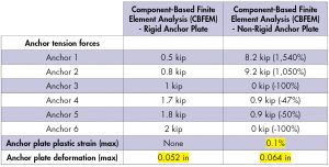
Interpretation of Results:
a) Higher anchor forces as expected with a non-rigid assumption via CBFEM.
b) % Plastic strain limit is 0.1. This indicates that the inelastic behavior has initiated, and yielding of the base plate should be expected. How much inelastic behavior and yielding can be allowed for plate behavior to be categorized as Close-to-Rigid? The CBFEM gives an option to set that limit and, by default, places an upper limit of 5% plastic strain. However, again, examine the von Mises stress. This value is 36.028 ksi, which shows that the result is just past the yield point (36 ksi) on the bi-linear stress-strain curve. From a stress/loading perspective, it is positioned very close to the start of the second portion of the curve. Position-wise, it is close enough to the inflection point between rigid and non-rigid behavior; this can be classified as Close-to-Rigid.
c) Absolute deflection for the non-rigid case is higher than that of the rigid case. This is expected as the yielding of the plate has initiated. However, it is not higher by a factor of 10. Therefore, for all practical purposes, it is still within an acceptable limit.
d) Summarizing the results from the parameters above, this non-rigid base plate behavior can be classified as Close-to-Rigid.
Engineering judgment based on experience is a crucial factor here, without a doubt. The software can be utilized (as illustrated above with the examples) to assist the design professional in understanding the parameters associated with a non-rigid base plate analysis, thus helping to qualify a non-rigid plate behavior as Close-to-Rigid.
Summary
CBFEM assumes a non-rigid plate behavior and provides an alternative to the classical rigid base plate design methodology. This methodology can easily handle any combination of base plate loading and profile eccentricity and is not as limited as the classical rigid plate methodology. It also provides validation of rigid or non-rigid plate behavior, unlike any other method.
However, since steel design codes mandate loads to be calculated using a rigid plate assumption, understanding the CBFEM parameters is mandatory as CBFEM assists the design engineer in qualifying a non-rigid plate as Close-to-Rigid. This approach can then be used to design the anchorage per the Building Code Requirements for Structural Concrete (ACI 318), which is the primary goal.■
Calculations performed using HILTI PROFIS Engineering Software.