
A Review of Design Considerations
Grout pockets are man-made holes in concrete structures (pre-installed before concrete placement or drilled after concrete placement) to allow the installation of anchors. The main benefit of using grout pockets is to allow equipment or structures to be installed after the concrete placement, providing more construction/installation schedule flexibility. In many non-modular projects, the equipment/machinery packages are typically completed and arrive at the construction site after most of the civil works at the site (including foundations) are completed. The grout pockets also provide extra installation tolerances and eliminate the risk of cast-in-place anchor movement during a foundation placement.
From a size perspective, there are generally two different grout pockets:
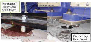
- Large grout pockets: The pocket size is much larger than the anchor, and pockets are typically pre-formed prior to the concrete placement, or they may be cored after the concrete placement. An example of the use of this pocket is with heavy machinery foundations (Figure 1). Typical diameters of large grout pockets are at least 3 to 4 times the anchor bolt diameter + 2⅜ inches [60 millimeters (mm)]. The use of 3 to 4 diameters approximately equates to the minimum size of the anchor head to resist a minimum of 70% of pretensioning force in high-strength anchor bolts (ASTM A-193 B7), which are commonly used for heavy machinery.
- Small grout pockets: the size of the pocket is slightly larger than the anchor and typically drilled. A common use is with post-installed bonded/adhesive anchors or reinforcing bars. Typically, optimal performance of adhesive anchors is achieved with a relatively thin bond line, that is, with an annular gap of 1⁄16 to ⅛ inch. The design of small grout pockets, including required depth, diameter, and surface preparation, is typically provided by the post-installed anchor manufacturer as part of the installation procedure and is not discussed in this article.
Chapter 17 of the American Concrete Institute’s ACI 318-19, Building Code Requirements for Structural Concrete and Commentary, does not provide the specific guidelines for designing large anchorage grout pockets. Without a detailed procedure or design guideline for designing and constructing large grout pockets in any industry standard, it is important to provide practical large grout pocket design methods to ensure safe designs.
The American Institute of Steel Construction’s (AISC) Design Guide 1, 2nd Edition: Base Plate and Anchor Rod Design (Guide 1), covers another type of grout pocket that is not discussed in this article: shear lugs embedded in a grout pocket in a concrete pedestal. Unfortunately, Guide 1 does not provide specific guidance on grout pocket design and sizing, other than recommending that the grout pockets be of sufficient size for ease of grout placement. Guide 1 also recommends that non-shrink grout have a flowable consistency.
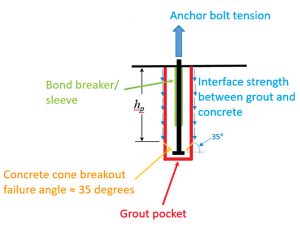
This article presents methods for designing a typical large anchor grout pocket in reinforced concrete foundations supporting equipment/machinery. It presents a load transfer analysis model, addresses the failure modes to be checked (pullout strength, interface strength between grout and concrete), and discusses the effect of the clamping force of a skid beam to restrain grout-pocket pullout. Only headed anchors in large grout pockets are discussed herein (Figure 2).
Using Large Grout Pockets
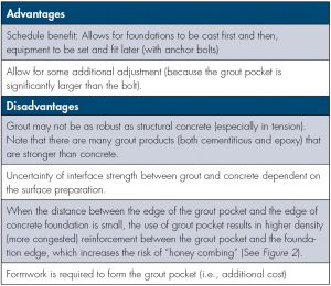
Absent industry standards and available literature with design guidance and procedures, there is little consistency in designing large grout pockets. From the authors’ experiences, large grout pockets are typically used to set equipment bases and are often specified by European equipment vendors. From a structural design perspective, no serviceability, performance, or strength benefit has been observed for grout pockets. The Table provides a summary of advantages and disadvantages of using large grout pockets.
Grout Pockets Construction
Grout pockets can be constructed in several ways: pre-installed during concrete placement using permanently installed corrugated pipes to form the pockets (common for large pockets) or drilled/cored (common for small pockets).
Before grouting, the pockets must be properly cleaned (from debris, oil, dust, etc.) to minimize the risk of voids or air-pocket formation around the anchor bolts. The pockets should be roughened, such as using steel brushes, to ensure proper bonding between grout and concrete. Corrugated pipes typically do not require roughening.
In general, cementitious grouts generally bond best to damp concrete, and polymer adhesives bond best to dry concrete (BASF, 2004).
Design Considerations
Tensile Load Transfer Analysis Model
For headed anchors, it is generally assumed that the entire tensile force is transferred through the anchor head bearing on the grout.
The design of headed grouted anchors generally follows the procedures for cast-in headed anchors, assuming that the governing failure mode is concrete breakout. The bearing stresses at the head of the anchor typically create sufficient outward pressure to generate substantial friction at the grout/concrete interface. Where the hole size is large, and there is a question about the bond between the grout and the concrete, a separate design check for bond failure may be appropriate (Zamora et al., 2003).
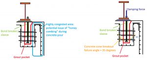
Where a threaded rod is used for the anchor, a sleeve or bond breaker is recommended. A sleeve may be used to provide an unbonded length for tensioning (Figures 2 and 3) and to avoid spalling at the concrete surface.
When grouts have a higher compressive strength than the foundation concrete, it is reasonable to use the 8 times f´c, (where f´c = specified 28-day compressive strength of concrete) for the bearing strength at the anchor head similar to the cast-in-place headed anchors pullout strength (i.e., Equation 17.6.3.2.2a of ACI 318-19) and the strength reduction φ-factor of 0.7 per Table 17.5.3(c) of ACI 318-19. The pullout strength determined from Equation 17.6.3.2.2a (ACI 318-19) corresponds to the force at which crushing of the concrete occurs because of the bearing of the anchor head.
Interface Strength between Grout and Concrete
For cement grout in the grout pocket, laboratory and field tests by Felt (1956) showed that bond strengths greater than 400 pounds per square inch (psi) might be achieved, regardless of the bonding medium, but that strengths of 200 psi or less may be adequate. Although these tests were performed based on cement grout, regardless of bonding types, the bond strength of 200 psi is generally used as a guide in designing bonding media (Suprenant, 1988). Thus, it is suggested to use 200-400 psi as the ultimate bond strength between grout and concrete.
European Forum Reciprocating Compressors (EFRC) report (2017) indicates that the cementitious or epoxy grout bond to the concrete foundation is stronger than the bond of the concrete to itself. Typically, concrete will separate next to the bond line of the grout concrete. Therefore, the weakest link in the bond of the grout (cementitious or epoxy) to concrete is the concrete itself. The force required to pull the concrete apart is called its shear strength Fv, and the minimum required grout pocket sizes, based on this bond strength, are as follows:
Fv = Interface surface area × vc
where Interface Surface Area is the surface area of the interface between grout pocket and surrounding concrete foundation.
For headed anchors, the interface surface area can be estimated from the intersection of the concrete breaking cone (35-degree angle per the Concrete Capacity Design [CCD] method of ACI 318) to the side of the grout pocket, as shown in Figure 3.
For square grout pockets:
Interface surface areasquare = 4 × bp × hp
For cylindrical grout pockets:
Interface surface areacylindrical = π × Dp × hp
where,
bp = square side dimension of the grout pocket
Dp = cylinder diameter of the grout pocket
hp = depth of the grout pocket, measured to the intersection of the breakout cone (Figure 3)
vc = the concrete shear strength
For typical normal concrete, vc can be taken as 2√f´c (in psi) as per ACI 318, where √f´c is the square root of specified compressive strength of concrete (psi).
The above formula provides the minimum required grout pocket size to avoid pulling out the entire pocket together with the anchor bolt.
When corrugated pipes are used, the interface strength can be higher. For example, test results show that the minimum ultimate interface strength between the winding pipe (one of the manufacturers is Kurimoto) and surrounding concrete is 460 psi or 3.2 MPa (Kouei Japan Trading Co, 2020).
For strength design, it is reasonable to use the strength reduction factor (φ) of 0.75.
Clamping Force to Restrain Pullout
In most machinery foundations, the largest tension force in the anchor bolts typically occurs during pretensioning. The purpose of the bolt pretensioning in machinery foundations is to keep the skid-frame tight to the foundation and maintain a sufficient friction force for any lateral component of the dynamic unbalanced forces and, therefore, reduce the risk of vibration. The bolt pretensioning force should also be larger than the maximum peak value of the sum of the dynamic loads in the vertical directions (EFRC Report, 2017). The EFRC report summarizes pre-load values from various references and recommends 70% of the bolt material yield stress for heavy machinery.
Unlike the net tension force on the anchor bolt during operation (i.e., due to uplift of the equipment), the pretensioning of the bolts of the machinery skid clamps down the skid beam to the concrete foundation, providing downward vertical force on top of the grout pocket, as shown in Figure 2.
The design engineer can consider accounting for the clamping force to reduce the required interface strength due to initial the pre-tensioning of anchor bolts, provided that:
- The skid beam is rigid, and the flange totally covers the grout pocket.
- There is no net tension or uplift under any load combinations during operation.
Still, as the skid beam flange often covers only part of the grout pocket, the grout pocket should be designed for the total pre-tensioning force.
Shear Load Transfer Analysis Model
When anchor bolts are pretensioned (common for machinery foundations), the friction between the bottom of the steel base plate and the top of the concrete foundation is commonly considered to resist shear force (due to wind, bundle-pull, seismic, etc.). However, it is generally not preferred to resist shear by the anchor bolt because of the flexibility of the anchor bolt and typical oversized holes on the steel base plate.
However, in cases where welded washers are used, and the anchor bolts are relied upon to resist shear, it is reasonable to use the CCD Method presented in Section 17.7 of ACI 318-19, provided that the grout strength is higher than the surrounding concrete foundation.
Minimum Edge Distance
The minimum distance between the edge of the grout pocket and the edge of concrete foundation should consider the following:
- Sufficient clear spacing to minimize the risk of honeycombing due to congested reinforcement (Figure 2). Depending on the magnitude of tensile and shear forces on the anchor, reinforcement surrounding the grout pocket may be required, and hence, sufficient space should be provided.
- The minimum edge distance of the headed anchors (Section 17.9 of ACI 318-19).
- Construction tolerance of grout pocket (e.g., 10 mm [⅜ inch] recommended in EFRC report (2017)).
EN 1992 Eurocode 2 specifies that the distance between the outer edge of the bolt pocket and the reinforcement steel is the minimum reinforcement diameter + 10 mm (⅜ inch).
Grout Materials
Grout materials with the following properties are recommended:
- Low peak exothermic temperature and low coefficient of thermal expansion grout. These properties are essential to minimize the expansion of grout and the associated risk of cracking a concrete foundation, especially between the edge of the grout pocket and the edge of the concrete foundation.
- A strength that is at least equal to the strength of concrete foundations. This strength property is important to minimize the risk of pre-mature failure of the headed anchor in the grout pocket (e.g., due to bearing/pullout failure).
- Flowable grout consistency is important to minimize the risk of voids in the grout pocket and at the underside of the equipment skid beams.
Summary
This article presents design considerations for large grout pockets, typically larger than approximately (3d to 4d) + 60 mm (2⅜ inch), where d is the anchor diameter. Large grout pockets in foundations supporting equipment/machinery provide more flexibility for the construction/installation schedule because it allows for equipment to be installed after the concrete foundation placement. In addition, large grout pockets increase available installation tolerances.
One of the critical parameters for designing large grout pockets for tension is the strength of the interface between the grout and the concrete foundations. Several recommended values are presented and illustrated by an example calculation. For future research, it is suggested that these recommended interface strength values be verified by large-scale tests.
European Forum Reciprocating Compressors (EFRC) report (2017) summarizes international guidelines, standards, and best practices for foundations, anchor bolts, and grouting of reciprocating compressor systems. It indicates that the tensile strength of concrete is relatively low. For example, the European standard, EN 1992-1-1 Eurocode 2, gives values for concrete with a compressive strength of 25 and 30 megapascals (MPa) (3,626 and 4,351 psi) and a tensile strength of respectively 1.8 and 2.0 MPa (261 and 290 psi) (5% fractile) up to 3.3 and 3.8 MPa (479 and 551 psi) (95% fractile).
Acknowledgments
The authors are grateful to Ramadan Ahmed. PEng., and David Johnson, P.E., from Dow Inc, and David Kerins, P.E. (LA) F.ASCE F.ACI from ExxonMobil for their contributions to review this article. The authors also thank Akihiro Yoshida, Sotaro Kitauchi, and Xiaojun Xu from JGC Corporation, Yokohama, and John Silva, P.E. and Justin Glover, E.I.T. from Hilti for various discussions and sharing useful information. The opinions, findings, conclusions, and recommendations provided in this article are from the authors and do not necessarily reflect the views of Dow, ExxonMobil, JGC Corporation, and Hilti.
Example Calculation
- Foundations with the specified concrete compressive strength of 5000 psi
- Non-shrink grout with the specified compressive strength of 5000 psi
- Anchor bolt: 1.5-inch diameter headed anchor bolt (ASTM A-193 Gr. B7) with an effective embedment depth of 33 inches and the total embedment depth of 40 inches.
- Factored net tension load on the anchor bolt: Pu = 110 kips
- Factored shear load: Vu = 0 kips because the shear is resisted by friction and the hole on the skid beam is oversized, and the washers are not welded to the skid beam
The required cylindrical grout pocket size is 12-inch diameter, 42-inch depth.
Also, to carry the 110 kips total factored net tension force, eight (8) Number 6 reinforcing bars (0.75-inch diameter), Grade 60, are required as anchor reinforcement. It is prudent and good practice to place anchor reinforcement as close as practical to the anchor. However, it is also suggested to keep the minimum distance between the outer edge of the grout pocket and the reinforcing bars of (rebar diameter + 10mm [⅜ inch]).■
References
ACI (American Concrete Institute). (2019). Building Code Requirements for Structural Concrete and Commentary, ACI 318-19. ACI, Farmington Hills, MI.
AISC (American Institute of Steel Construction). (2006). Steel Design Guide 1: Base Plate and Anchor Rod Design, Second edition. AISC.
BASF Building Systems. (2004). Adhesive and Grouted Fastener Capacity Design Guidelines.
CEN (European Committee for Standardisation). (2005). Eurocode 2 Design of Concrete Structures Part 1-1 General Rules and Rules for Buildings, EN 1992-1-1. CEN, Brussels, Belgium.
EFRC (European Forum Reciprocating Compressors). (2017). Report Summary of international guidelines, standards, and best practices of foundations, anchors, and grouting of reciprocating compressor systems. EFRC, Dresden, Germany, www.recip.org/wp-content/uploads/2020/04/EFRC-RD-Report-Foundation-Anchor-Bolts-Grouting-October-19th-2017.pdf (Nov 22, 2020)
Felt, E. J. (1956). “Resurfacing and patching concrete pavement with bonded concrete.” Highway Research Board Proceedings, 35, Highway Research Board, National Research Council, Washington, DC, 444-69. https://babel.hathitrust.org/cgi/pt?id=uc1.c101259926&view=1up&seq=7
Kouei Japan Trading Co. (2020). Kurimoto Winding Pipe, https://koueitrading.com/global/product/kurimoto-winding-pipe (Nov 22, 2020)
Suprenant, Bruce. (1988). Bonding new concrete to old, www.concreteconstruction.net/_view-object?id=00000153-8bab-dbf3-a177-9fbbc1ea0000 (Nov 22, 2020).
Zamora, N. A., Cook, R. A., Konz, R. C., & Consolazio, G. R. (2003). Behavior and Design of Single, Headed and Unheaded, Grouted Anchors under Tensile Load. ACI Structural Journal, 100 (2): 222-30. https://doi.org/10.14359/12486