
The building community has rediscovered the oldest building material – wood! Over the past decade, Cross-Laminated Timber (CLT) has gained momentum in the U.S., with over 500 projects currently in design or constructed to date. It is rare for a new building material like CLT to come along so quickly and become an integral part of the structural engineer’s toolbox. CLT has many advantages, including sustainability, speed of construction, strength, and beauty – all of which are the driving forces behind the doubling quantity of projects each year (www.woodworks.org, https://bit.ly/3wQCt8D). In addition, the desire to design sustainable and economic structures has many investors, designers, and builders captivated with CLT and wondering how they can find creative ways to integrate this material into their next project.

Elevator and Stair shafts
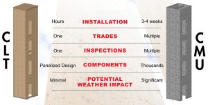
While a large percentage of CLT is being used in horizontal applications (floors and roofs), CLT can also be integrated into vertical applications such as exterior walls, shear walls, and elevator/stair shafts (Figure 1 and 2). Historically, shafts, typically designed and constructed out of concrete or CMU, have been disregarded elements of buildings. CLT, on the other hand, is an alternative approach worth considering. An elevator or stair shaft constructed of CLT offers inherent advantages in fire resistance, aesthetic appeal, and accelerated installation (Figure 3). Considering CLT is “hot off the press,” there are a few items worth discussing further.

Codes and Standards
Chapter 6 and 7 of the 2018 International Building Code (IBC) provides a prescriptive path to specify CLT as an approved building material for shaft construction. However, specific tests and documentation may be required from the CLT manufacturer. Code references for shafts and CLT allowance in building construction include:
- Chapter 6 of the IBC defines various construction types and allowable materials. CLT shafts meet the 2-hour fire-resistance rating (FRR) requirement for construction Types III, IV, and V.
- Chapter 7 of the IBC defines fire-resistance rating requirements.
- Section 713 – Shaft Enclosures: Section 713.2 provides the definition of a shaft enclosure to be detailed as a “fire barrier” in accordance with Section 707.
- Section 707 – Fire Barriers: Section 707.2 identifies that fire barriers shall be materials permitted by the building type of construction. Section 707.3 further defines the fire-resistance rating requirements indicating that shafts must comply with Section 713.4.
- Section 713.4 – Fire-Resistance Rating: This code section outlines that shaft enclosures must meet a 2-hour FRR when connecting 4 or more stories. This story requirement includes basements but not mezzanines. Furthermore, shaft enclosures must have an FRR that meets or exceeds the floor assembly it penetrates but does not need to exceed 2-hours. Lastly, it notes that shaft enclosures must meet the requirements of Section 703.2.1.
- Sections 703.2 and 703.3 define fire-resistance rating and methods for determining a fire-resistance rating. For CLT, the most popular methods are the ASTM E119 Test and Char Calculations per Chapter 16 of the NDS. Each CLT manufacturer should have testing data to meet the requirements outlined in ASTM E119.
If the shaft is incorporated as part of the Lateral Force Resisting System (LFRS), an Alternative Materials and Methods Request (AMMR) may be required per 2018 IBC Section 104.11. Check with the local Authority Having Jurisdiction (AHJ). Many AHJ’s allow CLT shear walls when low response factors for seismic design are used. Since CLT panels are made of wood, one common misconception is that they can be modeled as flexible. This is the case for conventional light-frame wood structural panel shear walls, but not for rigid CLT panels, which can be fabricated up to 10 feet wide, 52 feet tall, and 123⁄8 inches thick.
If AMMR is required per the AHJ, a common question arises: “What is the best path for achieving approval?” A few suggestions:
- Since this application is relatively new to most parties, it can take additional effort and time to get approved. Take this into consideration when determining the design schedule.
- Discuss CLT shaft options with the AHJ early in the design process. Then, if required, complete paperwork (provided by AHJ) to meet Section 104.11 requirements of the 2018 IBC.
- Reference future codes as part of your documentation, including the 2021 IBC, 2021 ANSI/AWC Special Design Provisions for Wind and Seismic (SDPWS), and ASCE 7-22, Minimum Design Loads for Buildings and Other Structures.
- ASCE 7-22 provides response factors for CLT to be used as LFRS for seismic design. Aspect ratios and special detailing are required. Response Modification Coefficient (R) equals 3.0 for normal shear walls and 4.0 for high aspect ratio shear walls. For wind-controlled design, the response is not a concern.
- 2021 SDPWS provides special detailing and aspect ratios, while items such as in-plane shear and connection capacity values must be calculated based on engineering mechanics. Check with the CLT manufacturer for published in-plane shear capacity values.
- For seismic-controlled design, try to isolate CLT shaft walls from the main LFRS to lessen the impact on the overall building response.
- Early on, verify that the CLT manufacturer has an ICC-ES report, as this information is typically required by the AHJ, specifically in high seismic regions.
- For a specific example of coordinating with the AHJ, go to the WoodWorks presentation on the Burwell Center for Career Achievement. (reference mark 16:20 in the video https://vimeo.com/427874585)
Design and Detailing
Designing and detailing CLT shafts may seem overwhelming, but it can and should be simple. Most CLT manufacturers can support/assist with design and detailing to meet the gravity, lateral, and fire-resistance considerations outlined within this article. In addition, they should assist with acoustical related items and provide design guidance to help optimize the manufacturing and assembly process, which are imperative for a successful CLT project.
The architect and engineer should become familiar with the CLT option early in the design process. To save time and money, it is best practice to integrate CLT shafts into the project during the initial project design and detailing. Regardless, the CLT manufacturer should provide all the information needed to successfully design CLT shafts, whether they are incorporated into the initial design or are substituting another system.
Detailing the CLT shaft is critical to meet minimum code requirements and significantly impacts the ease of installation.
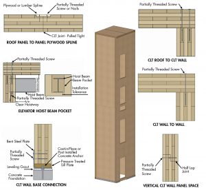
Figure 4 identifies an elevator shaft example and simple assembly details used to construct a CLT shaft. Stair shafts will have similar construction details. The CLT panel-to-panel connections are made with readily available partially threaded screws. Prefabricated steel angles placed on adjustable cast-in-place or post-installed concrete anchors can be used for the CLT wall-panel-to-foundation connection. It is essential to have base adjustability to achieve the required elevation and level bearing surface for the CLT wall. Hoist beams, life-line beams, divider beams, and stair landing beams can be supported by wall pockets or face mount hangers. Beyond simple assembly details, there are a few other items architects and engineers should consider.
- Shaft Size and Height: For shafts that are less than 4 stories, a single CLT panel can be installed to extend from the foundation to the top of the shaft. The number of panels provided on each side of the shaft will depend on the required size of the shaft. In the example provided (Figure 3), installing a single cab elevator shaft with only 5 panels, 4 walls, and a cap is possible. When shafts are 4 stories or more, a horizontal joint will be necessary to stack panels vertically. This is because the wall height will create temporary bracing challenges and push the limits of CLT manufacturing capabilities. Installing vertical segments as the other building construction goes up allows for improved job site safety and ease of installation.
- Fire-Resistance Rating Detail: For 1-hour fire-resistance-rated shafts using NDS Chapter 16 char calculations or ASTM E119 tested panels, the CLT can generally remain exposed. For a 2-hour fire-resistance-rated shaft, consult the CLT manufacturer to review specific ASTM E-119 detailing. It may be possible to leave the CLT wall panels exposed; however, special detailing considerations will likely be required.
- Acoustic Details: CLT alone may not provide the requisite Sound Transmission Class (STC) wall rating to meet minimum code values depending on the application. In these cases, additional wall assembly detailing may be necessary. Many times, this detailing is already part of the building system (e.g., a simple stud wall assembly adjacent to the CLT shaft) and will not become a special detailing requirement. Consult your CLT manufacturer for additional direction regarding STC wall rating assemblies
Conclusion
As CLT continues to gain traction in the U.S., those within the architectural, engineering, and construction communities continue to seek new ways to integrate this material into projects. With some specific items considered, CLT elevator and stair shafts offer a unique and simple way to incorporate CLT into traditional building structural systems. The key to success is early engagement with the AHJ and the CLT manufacturer to ensure the CLT shaft design process goes smoothly.
For more information on elevator and stair shafts, please visit: https://bit.ly/3hx6uWb.■