
The Real Failure Mode
A young researcher studying Buckling Restrained Braces (BRB) once commented that a change made in their design had improved the failure mode such that fatigue of the yielding core no longer controlled the BRB’s performance. Upon investigation, the change had simply created a failure mechanism that developed BEFORE the steel would have fatigued had the change not been made. The fatigue life of the BRB had not changed – the rest of the system simply no longer had the capacity to survive until fatigue limits would have been reached. Thus, what was thought to be a benefit, was not. But the point is an important one.
BRBs are tested primarily to confirm the relationship between strain and the overstrength generated in the steel core (known as a backbone curve), to measure the cumulative inelastic ductility (CID) capacity (an item related to fatigue life), and to confirm the ability of the BRB to undergo inelastic rotations. Even with the damaging nature of AISC-type qualification tests, BRBs will commonly survive tests as high as 3% strain (a 6% strain range) and achieve CID values of 800 to 1000 – 3 or 4 times the code required value. BRBs often achieve even higher strains and CID values when tests are performed that mimic expected earthquake records. For example, in recent tests of full-scale BRBs subjected to earthquake records scaled to at least 100% of the Maximum Considered Earthquake (MCE), each specimen survived more than 10 EQ records while accumulating between 5 to 8 times the code required CID and experiencing peak strain ranges of up to 6.3%.
Such tests indicate that the CID and fatigue capacity of the BRB will likely not be the limiting factor in a BRB’s ability to resist even multiple earthquake events. These tests, however, are designed for just that – to check the fatigue life of a properly designed BRB’s core in a properly designed frame. But this fatigue life can only be realized if the frame surrounding the BRB has sufficient strength to allow the BRB’s core to reach its full overstrength while keeping demands within safe limits in the remainder of the BRB, the gusset, and the frame. BRB testing provisions do not intend to test the frame itself, and only limited requirements are made for the connections and gussets. For example, the commentary of AISC 341, Seismic Provisions for Structural Steel Buildings, makes statements such as “While the subsequent design of the gusset plate connection is itself a complicated issue and the subject of continuing investigation, it is not intended that these connections become the focus of the testing program.” And “For the purposes of utilizing previous test data to meet the requirements of this section, the requirements for similarity between the brace and subassemblage brace test specimen can be considered to exclude the steel core extension connection to the frame.” (See AISC 341-16 commentary section K3.3 – emphasis added.)
The AISC 341 seismic provisions contain limited requirements that certain elements of the testing program be preserved in design, such as for gusset bracing used in tests, but, as noted, the commentary is clear that it is not intended to extend these to the interaction of the BRB with the surrounding frame. Doing so would dramatically increase the required testing parameters to the extent that testing would become impractical.
Global Stability
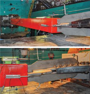
The interaction between the structural frame, the gusset plate, the BRB neck, and the BRB restrainer is complex and challenging to model adequately in testing. If these components are not accounted for adequately, they can form hinges creating a “global buckling” mechanism that occurs before the BRB core can reach its full overstrength potential – like the young researcher’s experience described above. Figure 1 shows a global stability failure of a BRB in testing. Notably, this specimen neither buckled at midspan nor did it experience local plate buckling, but instead plastic hinges formed at the gusset and neck, allowing the global mechanism to form.
To better predict when global buckling will occur, analytical models have been developed accounting for the strengths of the components affecting stability and their interaction with each other. Much of the work developing these models has been performed over the last 15+ years by a group of researchers under the direction of Professor Toru Takeuchi at the Tokyo Institute of Technology in Japan. Their model accounts for the rotational stiffness and strength of the many components involved, the reduced capacities of these components with increased axial forces, and the interaction of these components with each other. It is a plastic method that amplifies the initial geometric imperfection along the elastic buckling path until one of two plastic collapse mechanisms is reached. The method is understandably complex and can be difficult to implement. Iteration is also required to solve for the axial load at which the system becomes unstable. However, a known force (the compressive overstrength of the BRB, for example) can be used without iteration to determine whether it is above or below the stability point.
A simplification to this method, called the Notional Load Yield Line (NLYL) method, has been developed by Bo Dowswell with Arc International. This method combines many parts of the Takeuchi method with a simplified notional load model for the gusset plate capacity. This method has been adopted further by a group at the University of Canterbury, NZ, under the direction of Professor Charles Clifton, to apply the deformed shapes and associated strain energies of the Takeuchi method. This method is a specialized case of Takeuchi’s method with several simplifying assumptions to improve the usability for practicing engineers. It also adds a local gusset plate buckling check, which may govern for extended unstiffened gussets.
Strength and Embedment
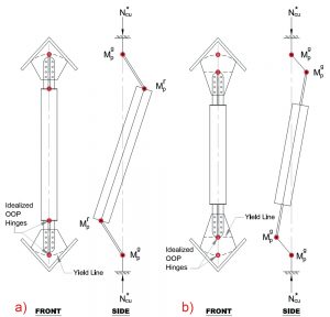
The NLYL and Takeuchi’s methods both address global stability by accounting for the formation of hinges within the system. These hinges may form at either end of the brace in the gusset plates, in the neck, or at the neck’s insertion into the restrainer. Once three hinges form, a mechanism will develop, leading to global instability. An asymmetric mode of instability, as shown in Figure 2, typically requires the least energy to form and therefore usually controls design. Hinges that form in this mode are located at and based upon the strength of the plastic moment capacity of the gusset (Mgp) and the moment transfer capacity of the restrainer (Mrp). The latter is controlled by the axial-flexural capacity of the BRB neck and the flexural capacity of the restrainer. Which one governs depends on the embedment length of the neck into the restrainer.
This embedment length introduces a critical element to BRB design that has not been considered expressly before the development of analytical global stability methods. This embedment is similar to cantilevering a steel beam from a concrete wall. If a deep enough insertion into the wall exists, the beam’s full moment capacity can be developed. However, if the insertion length is short, the material surrounding the hole may not have sufficient strength to develop the beam completely. In the case with sufficient embedment length, the moment capacity of the beam itself dictates the capacity. But when the embedment length is insufficient, the strength of the material surrounding the beam limits the capacity, and a premature failure of this material “blowing out” around the insertion zone occurs.
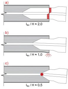
The cantilevered element’s moment capacity is related to its height, and so the “embedment ratio” can be introduced as a means to express the relative level of embedment. This ratio is taken as the length of the embedded element (in the direction that stability is being considered) to its height. The Takeuchi research notes that embedment ratios around 2.0 are considered sufficient to develop the neck such that its full moment capacity can be achieved. However, ratios less than 2.0 may also develop in the neck, especially in the presence of a stiff restrainer. As this ratio is reduced, however, it becomes increasingly difficult to develop the strength of the neck. Embedment ratios around 1.0 are likely to result in a premature plastic failure of the restrainer wall with the capacity dictated by the retainer strength. An embedment ratio nearing 0.5 will act like having a pin at the face of the restrainer cap plate, permitting rotations in the neck and with little or no moment capacity. These embedment ratios are shown schematically in Figure 3. Note that both methods calculate the moment capacity expressly using the insertion length (Lin) and the neck/restrainer strength. As such, specifying a value of the embedment ratio itself is not necessary.
The NLYL method involves two general mechanisms – plastic failure above, or “over” the yield line (OYL) and gusset buckling “under” the yield line (UYL). These can be seen in Figure 2, where Figure 2a shows an OYL-type mechanism and Figure 2b shows a UYL-type mechanism. In the OYL failure mechanism, one plastic hinge forms at the yield line in the gusset, and a second plastic hinge forms in the neck of the BRB. Thus, the hinging is above or “over” the yield line. In the UYL mechanism, a plastic hinge forms at the yield line in the gusset at the tip of the brace, and a second forms in the gusset below and the gusset buckles between the two. Thus the hinging is below or “under” the yield line. This latter mechanism is independent of the BRB, as it develops with hinges only in the gusset and is identical to local gusset plate buckling studied for years. The capacity side of the global stability equation is the summation of the effective moment transfer capacity of the restrainer (Mrp) plus a reduced gusset capacity (Mgp) for the OYL mechanism, or twice the reduced gusset capacity for the UYL mechanism. The reduced gusset capacity is a function of the gusset bending strength, including the axial force effect plus the destabilizing effect of the neck misalignment. (In the case of the UYL mechanism, the destabilizing effect on the reduced gusset capacity is included only once.)
In both failure mechanisms, the strengths of the elements and their initial out-of-straightness are considered to determine the total imperfection angle. The notional load used in the NLYL methods is a function of the total imperfection angle multiplied by the axial load (including overstrength) in the BRB core. The demand on the system is then generally in the form of the notional load multiplied by a moment arm and a second-order term (similar to the B2 factor used in stability analysis). When the demand exceeds the capacity, global instability is assumed to occur.
Conclusion
Global stability calculations can tell us a lot about a BRBF’s performance. For example, a flexible gusset may remain stable in the presence of a strong neck with proper embedment into a stiff restrainer since a hinge would need to form in each for instability to occur. Similarly, a weaker neck may be acceptable in the presence of good embedment, a strong restrainer, and a stiff gusset. In the absence of global stability checks, assessing the individual components in isolation might have suggested that the system was not acceptable when it was. Conversely, investigating the global stability of the system may reveal a weakness that would not be apparent when considering only the limit states of individual elements in isolation. These checks analyze the BRB frame holistically and help ensure that undesirable failure modes will be precluded, allowing energy dissipation to remain focused in the BRB core as intended.■
The significant contributions of the following individuals are acknowledged in furthering the research into BRB global stability and their assistance in the writing of this article.
Bo Dowswell – ARC International
Ben Sitler – Tokyo Institute of Technology
Charles Clifton – University of Canterbury
Behnam Zaboli – University of Canterbury